
Sowing streamline apparatus

A technology of assembly line and seeding mechanism, which is applied in the direction of interval-type quantitative seeding machinery and other directions, can solve problems such as affecting seed growth, production offset of sowing position, and complex mechanism structure.

Inactive Publication Date: 2013-02-27
余继琅
View PDF6 Cites 7 Cited by
  • Summary
  • Abstract
  • Description
  • Claims
  • Application Information

AI Technical Summary

Problems solved by technology

[0002] At present, in the process of modern agricultural mechanized production, a sowing assembly line is needed. The current sowing assembly line mainly includes mechanisms such as soil loading, hole pressing, sowing, soil covering, watering, and tray discharge; the soil loading mechanism of the existing sowing assembly line needs to be manually The soil is transported into the barrel of the soil loading mechanism. Due to the high position of the barrel in the normal state, the soil handling work requires a lot of physical strength, and labor with low strength is not suitable for this work; in addition, the existing seeding mechanism generally The work of sucking seeds and sowing is accomplished through the swing of the mechanical arm. The mechanism structure of the swinging back of the mechanical arm is more complicated, and the cost and maintenance cost are higher; Jumping, causing the position of sowing to shift production, affecting the future growth of future seeds

Method used


Image

  • Sowing streamline apparatus
  • Sowing streamline apparatus
  • Sowing streamline apparatus

Examples


Embodiment Construction

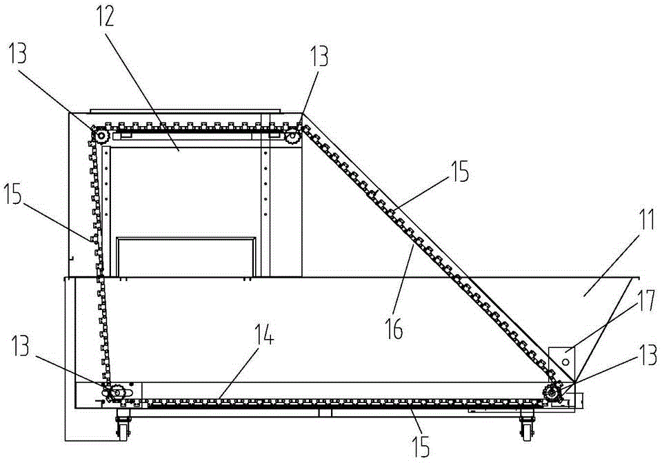
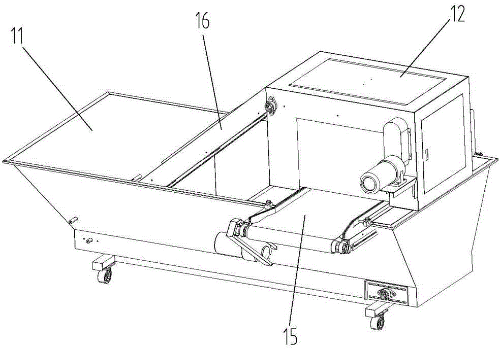
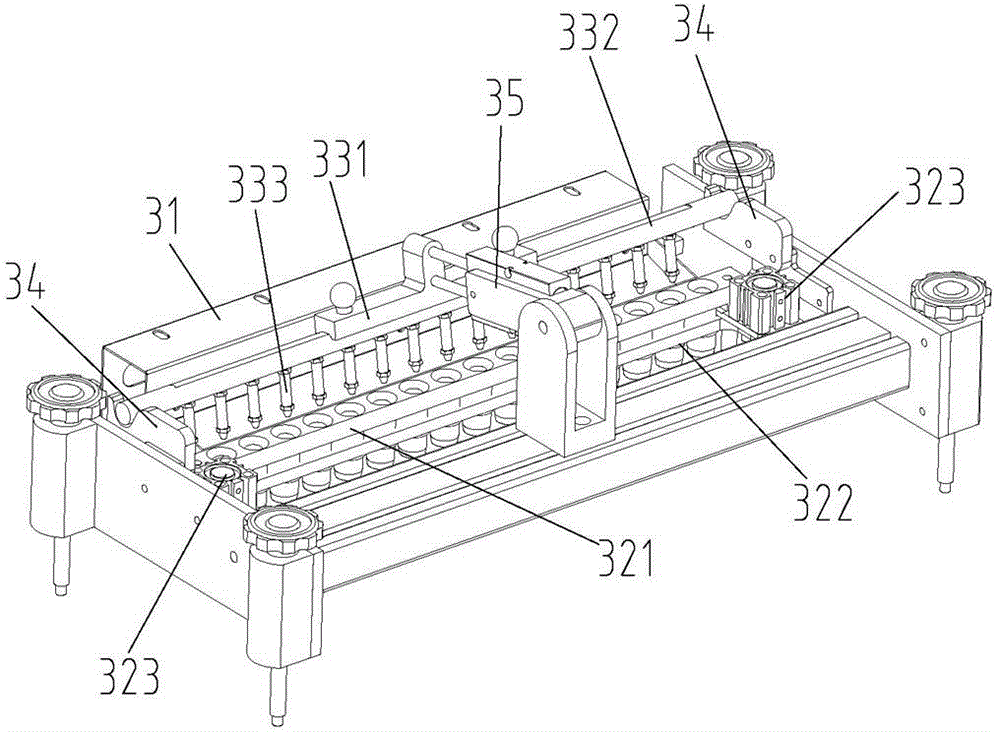
[0020] Such as figure 1 As shown in -7, a planting assembly line device mainly includes a soil loading mechanism 1, a seeding mechanism 3, a soil covering mechanism 2 and a sprinkler mechanism 4, and the conveyor belt devices 5 of each mechanism are connected end to end to form a transmission channel. The soil loading mechanism 1 includes a hopper 11, a conveyor belt device 5 and an upper soil hopper 12, the described upper soil hopper 12 is arranged above the conveyor belt 5 12, the described conveyor belt device 5 and the upper soil hopper 12 are arranged in the hopper 11, inside the hopper 11 The front and rear parts of the left and right ends are all provided with sprocket wheels 13, and the front and rear parts of the top left and right ends of the top of the upper soil hopper are also provided with sprocket wheels 13. A chain 14 matched with it is provided to form two sets of transmission chains, a number of partitions 15 are arranged in parallel between the two sets of ...


PUM


Abstract

The invention relates to a sowing streamline apparatus, mainly comprising a soil-loading mechanism, a sowing mechanism, a soil-covering mechanism and a watering mechanism. The conveyor belt apparatuses on all the mechanisms are connected end to end to form a conveying channel. The sowing streamline apparatus is characterized in that the soil-loading mechanism comprises a hopper, a conveyor belt apparatus and an soil-loading hopper, wherein the soil-loading hopper is disposed above the conveyor belt, the conveyor belt and the soil-loading hopper are disposed in the hopper, chain wheels are disposed at the front and rear portions of both the right and the left ends of the inner part of the hopper; chain wheels are also disposed at the front and rear portions of both the right and the left ends of the top of the soil-loading hopper; two groups of conveying chain mechanisms are formed by chains cooperated with the four chain wheels at the front portions and the four chain wheels at the rear portions; a plurality of separator plates are disposed between two chains of the front chain and the rear chain; a slope is arranged between the chains at the right sides of the hopper and the soil-loading hopper; the separator plates are disposed at the position of the slope and is tightly close to the surface of the slope; and the chain wheels are equipped with power devices. The sowing streamline apparatus simplifies the structure of the sowing mechanism by employing the soil-loading mechanism capable of carrying soil automatically, and guarantees the sowing position not to shift every time by additionally arranging a seeding movable mechanism, thereby increasing sowing efficiency.

Description

technical field [0001] The invention relates to agricultural machinery, in particular to a planting assembly line device. Background technique [0002] At present, in the process of modern agricultural mechanized production, a sowing assembly line is needed. The current sowing assembly line mainly includes mechanisms such as soil loading, hole pressing, sowing, soil covering, watering, and tray discharge; the soil loading mechanism of the existing sowing assembly line needs to be manually The soil is transported into the barrel of the soil loading mechanism. Due to the high position of the barrel in the normal state, the soil handling work requires a lot of physical strength, and labor with low strength is not suitable for this work; in addition, the existing seeding mechanism generally The work of sucking seeds and sowing is accomplished through the swing of the mechanical arm. The mechanism structure of the swinging back of the mechanical arm is more complicated, and the c...

Claims


Application Information

Patent Timeline
IPC IPC(8): A01C7/18
Inventor 余继琅
Owner 余继琅
Learn More