
Laser transmission welding follow-up clamping device

A technology of laser transmission welding and clamping device, which is applied in the field of laser welding, can solve the problems of easy-wearing glass ball optical properties, inability to realize three-dimensional weld seam welding, and unstable welding quality, and achieve compact structure, stable weld seam quality, Versatile effect

Inactive Publication Date: 2015-04-22
JIANGSU UNIV
View PDF7 Cites 0 Cited by
  • Summary
  • Abstract
  • Description
  • Claims
  • Application Information

AI Technical Summary

Problems solved by technology

The disadvantage is that it can only weld some planar welds (that is, the surface is required to be flat), and cannot realize the welding of three-dimensional welds; another example is the Globo spherical welding device invented by Leister, which has a glass ball at the welding head. The glass ball has the dual effect of focusing the laser beam and exerting a mechanical clamping force on the weld seam
The advantage is that it can realize the connection of any three-dimensional weld seam and has high flexibility, but it adopts single-sided clamping. For some workpieces with low rigidity, too small clamping force may cause welding failure, and excessive clamping force may cause The workpiece is deformed, and the point contact force is relatively concentrated, which leads to the stress concentration after welding. In addition, because the glass ball is used as both mechanical clamping and optical focusing, the long-term rolling friction is easy to wear the glass ball and make the optical performance worse, resulting in unstable welding quality.

Method used


Image

  • Laser transmission welding follow-up clamping device
  • Laser transmission welding follow-up clamping device
  • Laser transmission welding follow-up clamping device

Examples


Embodiment Construction

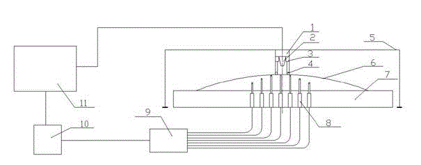
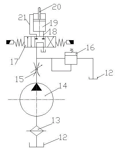
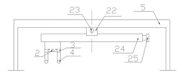
[0020] Such as figure 1 As shown, the laser transmission welding follower fixture includes a PC 11 , a PLC controller 10 , a hydraulic control system 9 , a support assembly, a pressure head assembly, a pressure head fixing assembly and a bracket 5 . The support assembly includes a small hydraulic thimble assembly 8 and a support plate 7; the indenter assembly includes a laser head base 1, a laser head 2, a pressure sensor 3 and a pressure roller 4; the indenter fixing assembly has two There are two schemes, the first scheme is called fixed style, and the second scheme is called free style. The specific implementation scheme is described with the first scheme.

[0021] A square array of holes is opened on the support plate 7, and a small hydraulic thimble assembly 8 is placed in the holes. Each hydraulic small thimble assembly has a specific number and can be individually controlled through a program. When the ejector bar is in the retracted position, the top end of the ejec...


PUM


Abstract

The invention provides a laser transmission welding follow-up clamping device, which is a welding and clamping device used for laser transmission welding plastic material or plastic and metal plastic. The device is characterized by comprising a support assembly, a pressure head assembly and a pressure head fixing assembly; the support assembly consists of hydraulic thimble components which are arranged in a square array and a support plate; each hydraulic thimble component schedules any one hydraulic thimble component through a PC (personal computer) terminal program; the overall support plate is controlled by a hydraulic control system to perform Z-directional movement; the pressure head assembly consists of a laser head, a pressure sensor and a compressing small roller wheel; the pressure head component performs X and Y directional movement under the driven of a servo motor; the compressing roller wheel can be adaptively adjusted at Z direction, so as to interact with a follow-up thimble under the compressing roller wheel to realize follow-up clamping for workpieces. According to the device provided by the invention, the extension height of the thimble rod required to be adjusted is satisfied, thus, the workpiece in any shapes can be adapted by the device, and the clamping problem of the curved surface type welding seam can be effectively solved.

Description

technical field [0001] The invention relates to the field of laser welding technology, in particular to a clamping device for laser transmission welding of plastic materials or plastic and metal materials, which is designed for some flat or curved weld seams, and can be adjusted according to the shape of the weld seam. This kind of weld usually cannot use common pressing mechanism, such as pressing glass, pressing plate mechanism. Background technique [0002] Laser transmission welding uses a near-infrared laser as a heat source to weld two superimposed plastic parts together. The upper part is required to be transparent to the laser beam, while the lower part should absorb the laser as much as possible. Laser transmission welding has many advantages such as fast welding speed, high precision, no pollution, non-contact welding, freedom and flexibility, etc. Therefore, laser transmission welding is just suitable for large-scale integration, automation and environmental ...

Claims


Application Information

Patent Timeline
Patent Type & Authority Patents(China)
IPC IPC(8): B29C65/16
Inventor 李品严长任国栋沈宗保刘会霞陈浩黄创赵振关王霄
Owner JIANGSU UNIV
Learn More