Device for limiting and protecting anchoring end of vertical steel strand

A technology of limit protection and steel strands, which is applied to bridge parts, bridges, buildings, etc., can solve problems such as inability to stick and fix, steel strands and clips slipping, and limited strength of the tape, so as to prevent the grout from entering The tunnel, the connection is tight and no slurry leakage, the effect of convenient and quick installation

Active Publication Date: 2015-03-11
CHINA RAILWAY 21TH BUREAU GROUP
View PDF7 Cites 0 Cited by
  • Summary
  • Abstract
  • Description
  • Claims
  • Application Information

AI Technical Summary

Problems solved by technology

The limit protection of the anchorage end of the vertical steel strand is generally constructed by tape wrapping method. This method is easy to isolate the concrete from the anchorage end structure, forming a space, destroying the integrity of the concrete structure, and easy to use in the formed space. Moisture accumulates, causing corrosion of the anchorage end parts, which in turn affects the durability of the bridge
Due to the limited strength of the tape, the steel strand, anchor plate, anchor cup and clip cannot be fully adhered and fixed, causing the steel strand and the clip to slip off, making it impossible to stretch, and it is necessary to open a hole in the beam body and reinstall it.
In addition, during construction, sparks from electric welding, cutting, etc. may easily cause the tape to burn, resulting in failure of protection.

Method used


Image

  • Device for limiting and protecting anchoring end of vertical steel strand
  • Device for limiting and protecting anchoring end of vertical steel strand
  • Device for limiting and protecting anchoring end of vertical steel strand

Examples


Embodiment Construction

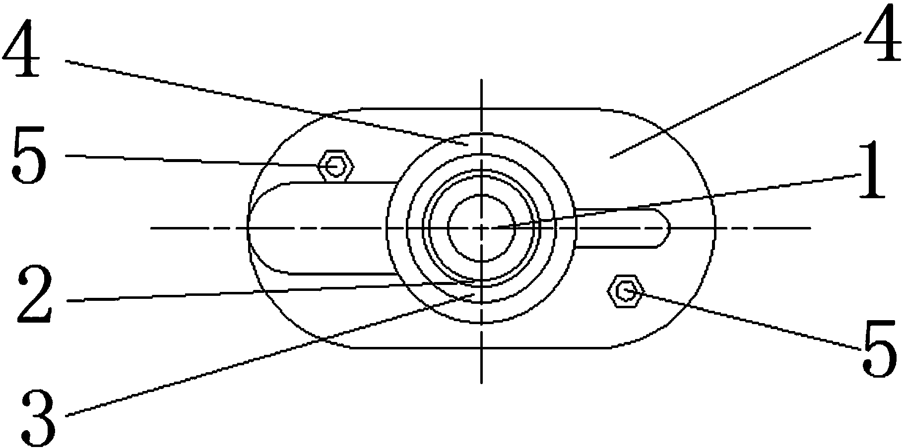
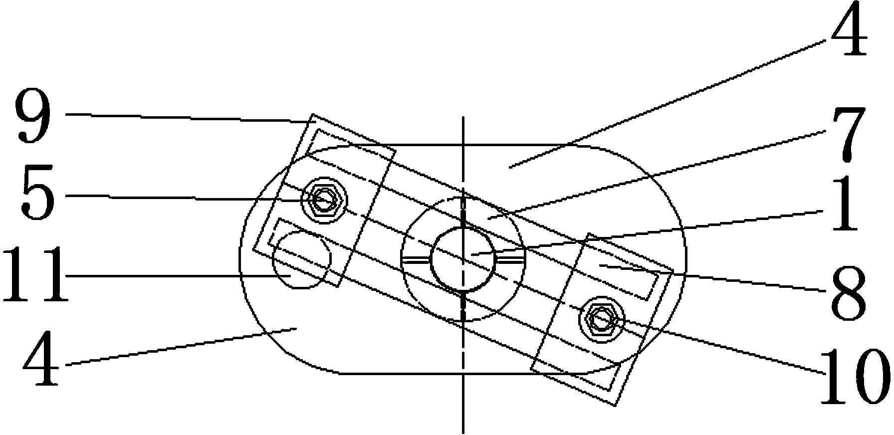
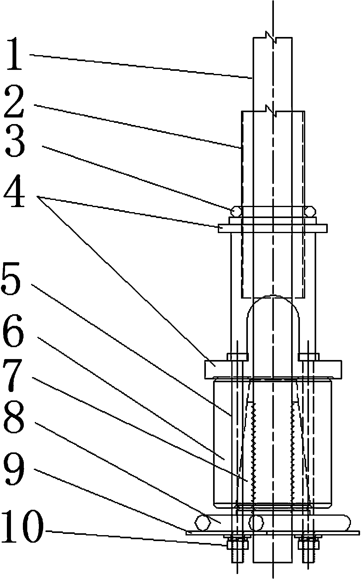
[0022] like figure 1 , figure 2 , image 3 and Figure 4 Shown: a limit protection device for the anchorage end of a vertical steel strand, including a steel strand 1, an iron pipe 2, an anchor pad 4, an anchor cup 6 and a clip 7, and the anchor pad 4 is provided with a grouting hole 11 ; Also includes a limit connecting plate 9, a limit rod 5 and a fastening nut 10; see Figure 5 , Figure 6 and Figure 7 : the limit connecting plate 9 is two steel plates 13 arranged on the left and the right, and two retaining rods 8 are welded above the two steel plates 13, the distance between the two retaining rods 8 and the distance between the two steel plates 13 form a through hole 12, and the two retaining rods The 8 spacing is smaller than the outer edge of the bottom of the clip 7 and greater than the outer edge of the steel strand 1, the steel strand 1 passes through the through hole 12, and the bottom of the clip 7 is stuck on the top of the two retaining rods 8 to limit the...


PUM


Abstract

The invention discloses a device for limiting and protecting an anchoring end of a vertical steel strand, belonging to the technical field of vertical bridge steel strand installation. The device comprises a steel strand, an iron sheet tube, an anchor bearing plate, an anchor cup and a clamping piece, and also comprises a limiting connecting plate, a limiting pull rod and a fastening nut, wherein a through hole is formed in the middle of the limiting connecting plate; the limiting connecting plate is arranged at the lower end of the anchor cup; the anchor bearing plate is fixedly connected with the limiting connecting plate by the limiting pull rod and the fastening nut; the size of the through hole is smaller than that of the outer edge of the bottom of the clamping piece and larger than that of the outer edge of the steel strand; the steel strand penetrates through the through hole; and the bottom of the clamping piece is clamped above the limiting connecting plate. The limiting connecting plate limits the downward movement of the clamping piece, and the anchor cup is tightly adhered to the anchor bearing plate and the clamping piece by using the limiting pull rod and the limiting connecting plate, so that the vertical prestress steel strand is tightly combined with the anchor cup and the clamping piece so as to form a group of relatively fixed overall structure, and the occlusion tightness is ensured; and moreover when the concrete is cast, grout does not leak into a mudjack duct and the clamping piece, so that the quality of construction is ensured. The device is simple in structure, rapid and convenient to install and convenient and economic in martial resource.

Description

technical field [0001] The invention belongs to the technical field of bridge vertical steel strand installation, and in particular relates to a position limiting protection device for the anchorage end of a vertical steel strand. Background technique [0002] At present, long-span bridges are gradually being promoted in my country, and the fine-rolled threaded steel bars used for vertical prestressing are gradually replaced by steel strands. The limit protection of the anchorage end of the vertical steel strand is generally constructed by tape wrapping method. This method is easy to isolate the concrete from the anchorage end structure, forming a space, destroying the integrity of the concrete structure, and easy to use in the formed space. Moisture accumulates, causing corrosion of the anchorage end parts, which in turn affects the durability of the bridge. Due to the limited strength of the tape, the steel strand, anchor plate, anchor cup and clip cannot be fully bonded ...

Claims


Application Information

Patent Timeline
Patent Type & Authority Patents(China)
IPC IPC(8): E01D19/14
Inventor 周明升马建会范登乾韩大栋宣建军肖祖芳张仲涛李东风孙江宁周征陈运李伟峰赵永辉马红叶
Owner CHINA RAILWAY 21TH BUREAU GROUP
Why Eureka
Try Eureka