Extremely high vacuum gauge calibration device and method

A technology of extremely high vacuum and calibration device, applied in the field of measurement, it can solve the problems of uncertainty and complex measurement links, and achieve the effect of accurate calibration, small measurement uncertainty, and widening the range of flow measurement.

Active Publication Date: 2013-02-27
NO 510 INST THE FIFTH RES INST OFCHINA AEROSPAE SCI & TECH
View PDF5 Cites 9 Cited by
  • Summary
  • Abstract
  • Description
  • Claims
  • Application Information

AI Technical Summary

Problems solved by technology

[0004] Compared with the dynamic flow method, the shunt method has the disadvantage that it needs to measure the conductance ratio of the two small holes on the shunt chamber, and the measurement process is more complicated, so it will cause additional uncertainty when measuring the flow rate.

Method used


Image

  • Extremely high vacuum gauge calibration device and method
  • Extremely high vacuum gauge calibration device and method
  • Extremely high vacuum gauge calibration device and method

Examples


Embodiment 1

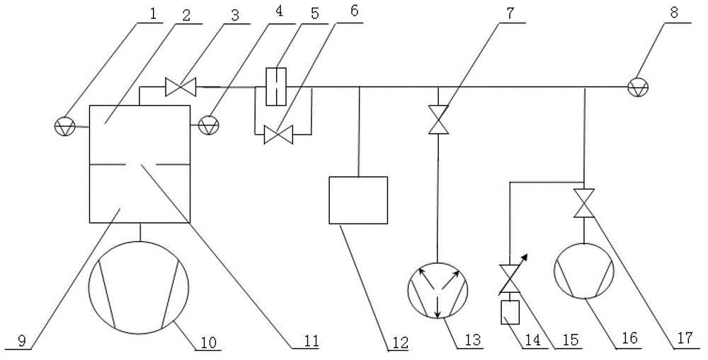
[0033] Such as figure 1 Said, a very high vacuum gauge calibration device, said device comprises: very high vacuum gauge 1, very high vacuum calibration chamber 2, first valve 3, calibrated vacuum gauge 4, small hole 5, second valve 6, The third valve 7, high-precision vacuum gauge 8, extremely high vacuum pumping chamber 9, very high vacuum pumping unit 10, flow limiting hole 11, voltage stabilizing chamber 12, non-evaporable getter pump 13, gas source 14, Fine-tuning valve 15, flow meter air extraction unit 16 and fourth valve 17, peripheral equipment including heating device;

[0034] Wherein, the extremely high vacuum pumping unit 10 is connected with the very high vacuum pumping chamber 9, the very high vacuum pumping chamber 9 is connected with the very high vacuum calibration chamber 2, the very high vacuum pumping chamber 9 is connected with the very high vacuum calibration chamber There is a flow limiting hole 11 in the middle of 2, the extremely high vacuum gauge 1 ...


PUM


Abstract

The invention discloses an extremely high vacuum gauge calibration device and a method, belonging to measurement field. The device comprises an extremely high vacuum gauge, an extremely high vacuum calibration room, a first valve, a vacuum gauge to be calibrated, a small hole, a second valve, a third valve, a high-precision vacuum gauge, an extremely high vacuum aspirating chamber, an extremely high vacuum air-bleed set, a flow limiting hole, a pressure stabilizing chamber, a non-evaporable getter pump, an air source, a micrometering valve, a flowmeter air-bleed set and a fourth valve, and the peripheral equipment includes a heating device. With the device and the method disclosed by the invention, the measurement uncertainty is small, accurate calibration to the extremely high vacuum gauge within the pressure range smaller than 10<-9>Pa can be realized, and the flow measurement range is expanded.

Description

technical field [0001] The invention relates to a device and a method for calibrating an extremely high vacuum gauge, in particular to a device and a method for realizing precise calibration of an extremely high vacuum gauge by using a dynamic flow method, and belongs to the field of measurement. Background technique [0002] In metrology laboratories, high-precision gas micro-flow meters are mostly used to measure and provide known gas flow rates. High-precision gas micro-flow meters mostly use constant-pressure gas micro-flow meters and fixed conductance gas micro-flow meters, and their measurement range is (1×10 -9 ~1×10 -4 ) Pa·m 3 / s. When the dynamic flow method is used to calibrate, due to the influence of the gas micro-flowmeter pipe inner wall degassing effect, the flow measurement lower limit is only 1×10 -9 Pa·m 3 / s, the lower limit of the calibration of the corresponding vacuum gauge is only 10 -8 Pa level, so the calibration of the extremely high vacuum g...

Claims


Application Information

Patent Timeline
Patent Type & Authority Applications(China)
IPC IPC(8): G01L27/00
Inventor 李得天成永军冯焱习振华赵澜管保国
Owner NO 510 INST THE FIFTH RES INST OFCHINA AEROSPAE SCI & TECH
Why Eureka
Try Eureka