Shale gas reservoir recovery simulation experimental device

A simulation experiment device and technology of shale gas reservoirs, applied in the field of shale gas reservoir mining simulation experiment devices, can solve the problem of few mining mechanisms

Inactive Publication Date: 2013-02-27
SOUTHWEST PETROLEUM UNIV
View PDF8 Cites 58 Cited by
  • Summary
  • Abstract
  • Description
  • Claims
  • Application Information

AI Technical Summary

Problems solved by technology

Due to the characteristics of shale gas, the current laboratory experimental research mainly includes petrological analysis, geochemical analysis, gas-bearing analysis, special analysis of tight rocks, etc., and comprehensive research on various recovery mechanisms of shale gas reservoirs in the laboratory , mining dynamics and other aspects are less

Method used


Image

  • Shale gas reservoir recovery simulation experimental device
  • Shale gas reservoir recovery simulation experimental device

Examples


example 1

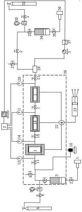
[0020] like figure 1 As shown, the present invention provides a simulation experiment device for simulating shale gas reservoir exploitation, including a high-pressure gas source system, an injection system, a model system, a constant temperature box system, a back pressure system and a data acquisition system.

[0021] The high-pressure gas source system mainly includes two parts, high-purity CH 4 / CO 2 / He high-pressure gas cylinder 5 is sequentially connected to valve 6, booster pump 8, and intermediate container 3 of the injection system; N 2 The high-pressure cylinder 32 is sequentially connected to the valve 31, the booster pump 29, and the intermediate container 34 of the back pressure system. The booster pumps (8, 29) are connected to the air compressors (7, 30), one end of the booster pumps (8, 29) is connected to the high-pressure gas cylinders (5, 32), and the other end is connected to the intermediate container (3, 34) , where the high-pressure gas cylinders (5,...

example 2

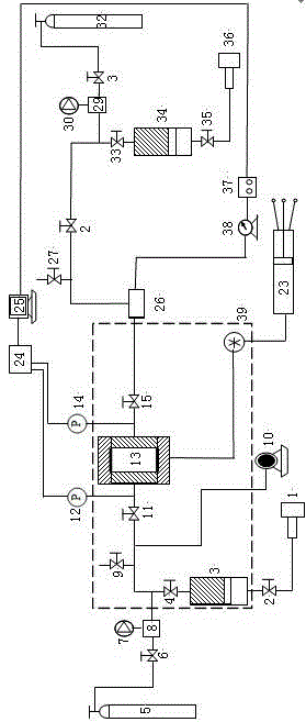
[0039] like figure 2As shown, the present invention also provides a schematic diagram of a shale gas adsorption / desorption experimental device, including a high-pressure gas source system, an injection system, a model system, a constant temperature box system, a back pressure system and a data acquisition system. The high-pressure gas source system, injection system, constant temperature box system, back pressure system and data acquisition system are partly the same as the shale gas reservoir mining simulation experiment device described in Example 1, and will not be described in detail. The inlet valve 11 in the model system is connected to the flat model rock core holder 13 and the outlet valve 15 in turn, the pressure sensor 12 and the pressure sensor 14 are respectively connected to the inlet and outlet of the flat model rock core holder 13, and the inlet valve 11 is connected to the injection system The intermediate container 3 is connected, the inlet valve 11 is connec...


PUM


Abstract

The invention relates to an experimental device in the field of natural gas recovery, and particularly relates to a shale gas reservoir recovery simulation experimental device. The shale gas reservoir recovery simulation experimental device comprises a high-pressure gas source system, an injection system, a model system, a thermostat system, a pressure return system and a data acquisition system, wherein an intermediate container in the injection system and a core holding unit in the model system are positioned in a thermostat. The shale gas reservoir recovery simulation experimental device has the advantages that a plate model core clamping device and two full-diameter core clamping devices are connected, the cores of different dimensions are connected in series, multi-scale pore characteristics in the shale gas reservoir can be simulated, the multi-scale characteristics of shale gas seepage influenced by the multi-scale effect are reflected, the recovery process of the shale gas reservoir can be accurately simulated, and recovery mechanisms and recovery dynamics of the shale gas reservoir in different modes can be comprehensively evaluated; and meanwhile, a large-scale shale core adsorption/desorption experiment can be performed by utilizing the experimental device, and a gas adsorption/desorption rule of the large-scale shale core under different conditions is researched.

Description

technical field [0001] The invention relates to an experimental device in the field of natural gas exploitation, in particular to a shale gas reservoir exploitation simulation experimental device. Background technique [0002] As a new type of unconventional energy source, shale gas has a mechanism of formation, migration, occurrence and exploitation different from conventional natural gas. It exists in mudstone, high-carbon mudstone, shale and interbedded silty mudstone, muddy In sandstone formations, shale gas reservoirs show a typical "in situ" accumulation mode as a result of the accumulation of natural gas nearby in the source rock formation after generation. The natural gas in shale gas reservoirs is mainly present in the surface of rock particles and organic matter in the adsorbed state, or in the pores and fractures in the free state, and there is also a very small amount in the dissolved state. The occurrence of adsorbed natural gas is closely related to the conten...

Claims


Application Information

Patent Timeline
Patent Type & Authority Applications(China)
IPC IPC(8): G01N33/24
Inventor 刘向君熊健梁利喜
Owner SOUTHWEST PETROLEUM UNIV
Why Eureka
Try Eureka