Wireless power transmission device

A technology of wireless power transmission and amplifying coils, applied in circuit devices, electrical components, electromagnetic wave systems, etc., can solve problems that are difficult to apply to high-power occasions, achieve high output power, reduce insulation costs, and simple design

Active Publication Date: 2013-02-27
INST OF ELECTRICAL ENG CHINESE ACAD OF SCI
View PDF5 Cites 17 Cited by
  • Summary
  • Abstract
  • Description
  • Claims
  • Application Information

AI Technical Summary

Problems solved by technology

[0007] The technical problem to be solved by the present invention is to provide a high-power wireless power transmission device to solve the problem that the current wireless power transmission technology is difficult to apply to high-power occasions (such as electric vehicle charging)

Method used


Image

  • Wireless power transmission device
  • Wireless power transmission device
  • Wireless power transmission device

Examples


Embodiment Construction

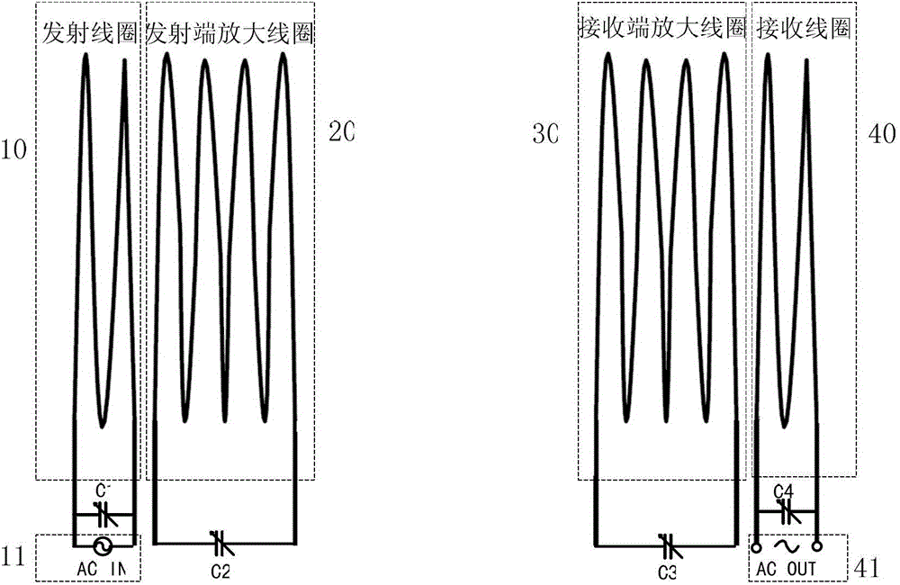
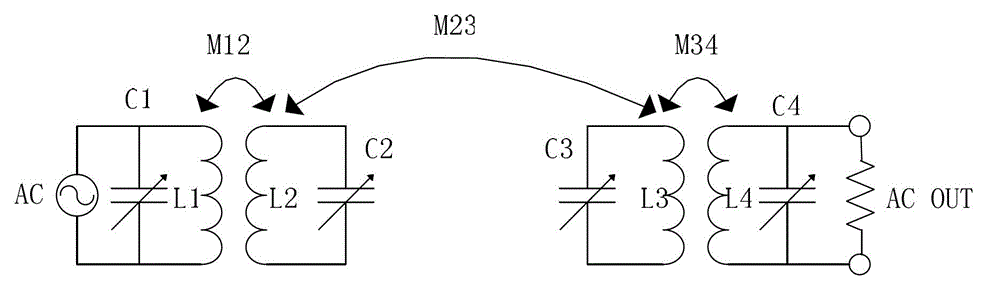
[0024] Such as figure 1 As shown, the device of the present invention is composed of four coils with resonant compensation capacitors, the coils are coupled by an air gap, a high-frequency AC power source 11 is provided at the front end of the transmitting coil, and a load 41 is connected to the rear end of the receiving coil.

[0025] The transmitting coil 10 and the transmitting-end amplifying coil 20 constitute a transmitting device, and the receiving-end amplifying coil 30 and the receiving coil 40 constitute a receiving device.

[0026] As an embodiment, four coils including the transmitting coil 10 , the transmitting-end amplifying coil 20 , the receiving-end amplifying coil 30 , and the receiving coil 40 are all wound into a helical coil with a diameter of 500 mm. The coil is wound by multiple strands of enameled wire, the number of turns of the transmitting coil 10 and the receiving coil 40 is 2 turns, and the number of winding turns of the transmitting-end amplifying ...


PUM


Abstract

The invention relates to a wireless power transmission device which is composed of four coils of a transmitting coil (10), a transmitting terminal amplifying coil (20), a receiving terminal amplifying coil (30) and a receiving coil (40) which are parallelly arranged, and the four coils are all in parallel connection with variable resonance compensation capacitors ( C1, C2, C3 and C4). The transmitting coil (10) and the transmitting terminal amplifying coil (20) form a transmitter, and the receiving terminal amplifying coil (30) and the receiving coil (40) form a receiver.

Description

technical field [0001] The invention relates to a wireless power transmission device with high power and high efficiency. Background technique [0002] Wireless power transmission has broad application prospects, but the existing wireless power transmission devices have low power, low efficiency, and short transmission distance, and are mainly used in electronic equipment charging applications. This technology is difficult to use in high-power applications. [0003] The application of wireless power transmission in high-power applications (such as electric vehicle charging) is of great significance, and it is also a research hotspot in recent years. However, this kind of application requires the wireless power transmission power to reach at least KW level, and this level of power transmission must require high power transmission efficiency, otherwise not only huge energy loss will be generated, but also the heat dissipation of the device is a difficult problem to solve. Exi...

Claims


Application Information

Patent Timeline
Patent Type & Authority Applications(China)
IPC IPC(8): H02J17/00H02J50/12
Inventor 廖承林王丽芳李均锋邓凯
Owner INST OF ELECTRICAL ENG CHINESE ACAD OF SCI
Why Eureka
Try Eureka