Device, method, and system for compressed air control and compressed air supply

A technology for compressed air and control devices, applied in air handling devices, pump/compressor arrangements, brake transmission devices, etc., to achieve the effects of easy starting process, short running time, and protection from corrosion damage

Inactive Publication Date: 2013-02-27
WABCO GMBH
View PDF7 Cites 12 Cited by
  • Summary
  • Abstract
  • Description
  • Claims
  • Application Information

AI Technical Summary

Problems solved by technology

[0011] In particular, the present invention solves this task with a novel compressed air control device or a new compressed air control method

Method used


Image

  • Device, method, and system for compressed air control and compressed air supply
  • Device, method, and system for compressed air control and compressed air supply
  • Device, method, and system for compressed air control and compressed air supply

Examples


Embodiment Construction

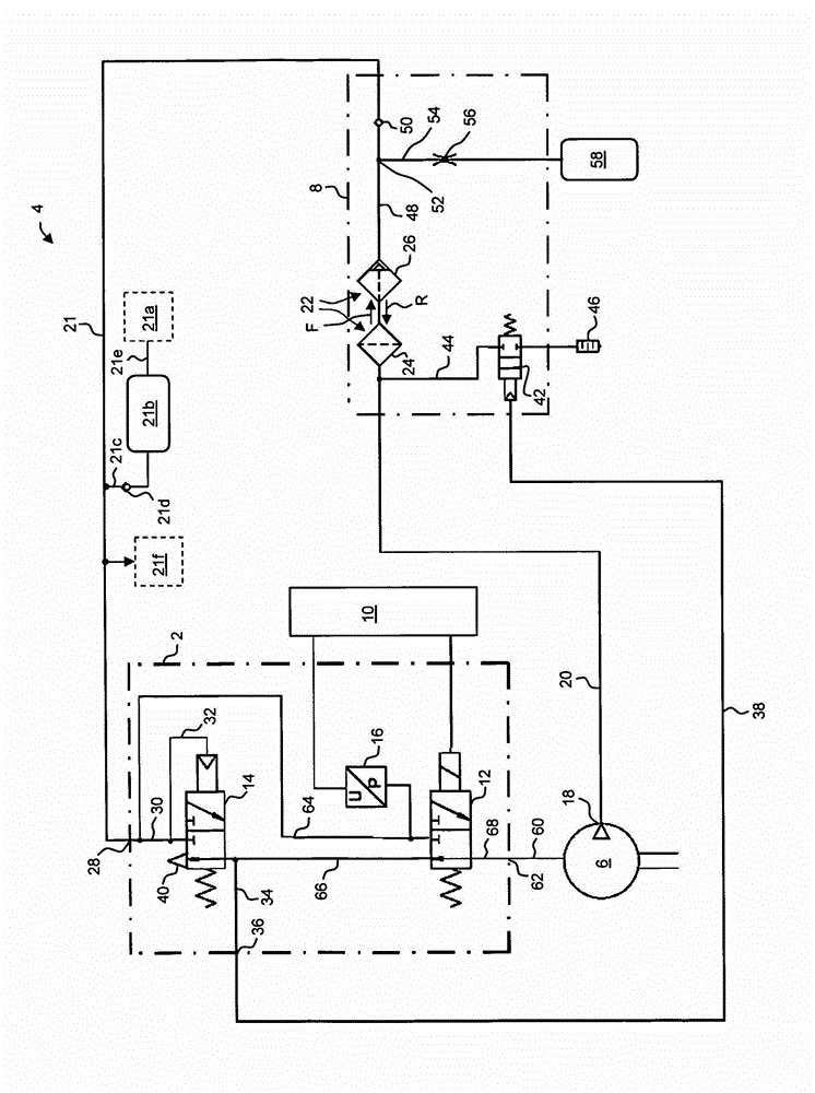
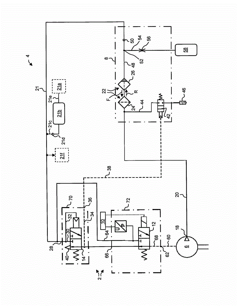
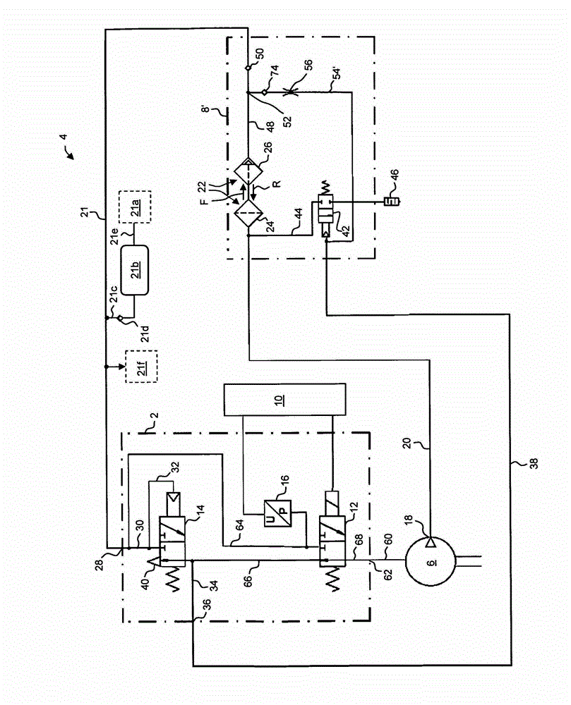
[0063] figure 1 Shown is a circuit diagram including a compressed air control device 2 according to the invention, with which, optionally with the aid of additional components of a compressed air supply system 4 with the compressed air control device 2 , the Compressed air control method. This compressed air supply system 4 additionally has a compressor 6 and an air drying device 8 .

[0064] The compressed air control unit 2 is controlled by an electronic control unit 10 . The compressed air control device 2 has, in particular, an electrically actuatable feed control valve 12 which can be switched electrically from the non-energized to the energized switching state by an electronic control unit 10 . In addition, the compressed air control device 2 has a so-called regulator or a pneumatically actuated discharge control valve 14 , which likewise can be switched between two switching states, but is pneumatically actuated. Finally, the compressed air control unit 2 also has a ...


PUM


Abstract

The invention relates to a compressed air control device (2) and to a compressed air control method for controlling respective operating states of a compressor (6) and of an air drying device (8) in a vehicle. The compressed air control device (2) has a compressor control outlet (36), by means of which the compressed air control device can be pneumatically connected to a control inlet of the compressor (6) in order to pneumatically switch the operating state of the compressor (6). The compressed air control device (2) further comprises a system pressure inlet (28), by means of which the compressed air control device can be pneumatically connected to a system pressure line (21), which conducts a system pressure produced by the compressor (6). The compressed air control device (2) further comprises a ventilation control outlet (36), by means of which the compressed air control device can be pneumatically connected to a control inlet of the air drying device (8) in order to pneumatically switch the operating state of the air drying device (8). Finally, the compressed air control device (2) also comprises a pneumatically operable ventilation control valve (14), by means of which the system pressure inlet (21) can be pneumatically connected to the ventilation control outlet (36) depending on the system pressure in order to switch the operating state of the air drying device (8). According to the invention, an electrically operable supply control valve (12) is provided in the compressed air control device (2).; By means of the supply control valve, the system pressure inlet (28) can be pneumatically connected to the compressor control outlet (62) independently of the system pressure in order to switch the operating state of the compressor (6). Thus, energy-saving operation of a compressed air supply system (4) comprising the compressed air control device (2) and the air drying device (8) by means of a compressed air supply method containing the compressed air control method is possible.

Description

technical field [0001] The invention relates to a compressed air control device for controlling the respective operating states of a compressor and an air drying device; a compressed air control method for operating said compressed air control device; an electronic control for controlling said compressed air control method Device; compressed air supply system with said compressed air control device and said electronic control device; compressed air supply method for operating said compressed air supply system and with said compressed air supply system or with said compressed air control device and the electronic control unit of the vehicle. Background technique [0002] In vehicles, especially trucks, the compressed air supply system is used to supply compressed air to the compressed air device or pneumatic system of the vehicle. Such compressed air devices are, for example, air spring devices and brake systems. [0003] This known compressed air supply system has a compre...

Claims


Application Information

Patent Timeline
Patent Type & Authority Applications(China)
IPC IPC(8): B60T13/68B60T17/00B60T17/02F04B49/02F04B49/22
CPCF16K31/12B60T17/004F04B49/22F04B49/022B60T17/02B60T17/00B60T17/002B60T13/683
Inventor 海因里希·迪卡梅伊尔康拉德·法伊尔阿本德
Owner WABCO GMBH
Why Eureka
Try Eureka