Electric lifting rod

A lifting rod and electric technology, applied in the field of lifting rods, can solve the problems of poor reliability and safety, limited lifting height, easy breakage of wire ropes, etc., and achieve reliable work, short lifting time and good anti-icing performance

Inactive Publication Date: 2013-03-06
南京俊东机电设备有限公司
View PDF2 Cites 14 Cited by
  • Summary
  • Abstract
  • Description
  • Claims
  • Application Information

AI Technical Summary

Problems solved by technology

[0002] Lifting rods have been widely used as a tool for quickly elevating antennas or lighting fixtures and other equipment. Most of the existing lifting rods are driven by wire ropes or ordinary screw rods, which require frequent locking and unlocking. The transmission efficiency is low, and the wire rope is easy to broken, the lifting rod is easy to "stuck", the failure rate is high, the reliability and safety are poor, and the height of the lifting is limited, and it will gradually slide down after the lifting is in place. Therefore, for those skilled in the art, it is always Constantly trying new methods to solve the above technical problems, but there has been no suitable technical solution

Method used


Image

  • Electric lifting rod
  • Electric lifting rod

Examples


Embodiment 1

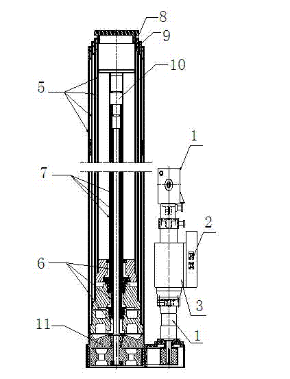
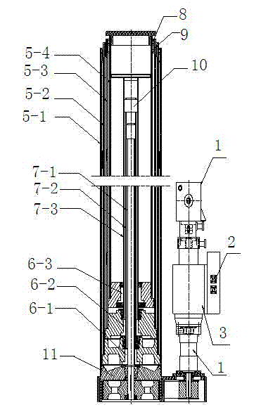
[0017] Example 1: Such as figure 1 A kind of electric elevating rod shown, comprises driving device and lifting device, and driving device comprises driving motor 3, speed reducer 4 and hand box 1, and lifting device comprises base 11, casing 5, transmission structure, casing 5 and transmission The structures are all connected to the base 11; the transmission structure includes a screw rod 7 and a screw nut 6, and the lifting device is a joint transmission structure through n sleeves, n-1 screw rods and n-1 screw nuts; the screw rod 7 It is fixedly connected with the screw nut 6, the screw nut 6 is fixedly connected with the base 11, the base 11 is fixedly connected with the bushing 5, different screw rods are connected through the transmission of the key 10, and different bushings are slidingly connected through the self-lubricating bearing 8. The unique self-lubricating bearing can reduce frictional resistance.

Embodiment 2

[0018] Example 2: Such as figure 1 As shown, the sleeve pipe of the present invention is a square tube with good guiding performance, good bending resistance and twist resistance performance of the rod body; Dustproof and other sealing functions; the upper end of the casing is provided with a limit block, which acts as a mechanical safety limit; the screw and the screw nut are rolling helical pairs of ball screws, which have high transmission efficiency, but are not self-locking. Brake motor 3 It has a safety locking function; the rise and fall of the lifting rod is realized by controlling the positive and negative rotation of the motor, and the upper and lower limit of the lifting rod is realized by an analog stroke device.

Embodiment 3

[0019] Example 3: As a further improvement of the present invention, the driving motor is a power-off brake motor 3, and the control switch adopted by the driving device is an analog travel limit switch. It can ensure the safe and self-locking work of lifting at any height, and ensure the safety of the limit position.


PUM


Abstract

The invention relates to an electric lifting rod, which comprises a driving device and a lifting device, wherein the driving device comprises a driving motor, a reduction box and a hand-cranking box; the lifting device comprises a base, casing pipes and a transmission structure; and the casing pipes and the transmission structure are both connected to the base. The electric lifting rod is characterized in that the transmission structure is set into a rolling spiral transmission structure, and the transmission structure comprises lead screws and nuts cooperatively and fixedly connected with the lead screws. The relative displacement of the casing pipes of the electric lifting rod disclosed by the invention is lead screw and nut transmission, other transmission modes, such as steel wire ropes, are omitted, and the electric lifting rod has the advantages of big load bearing capability, high reliability and safety, simple transmission structure and convenience in disassembling and maintaining, and multi-section lead screws are in invaginating transmission.

Description

technical field [0001] The invention relates to an elevating rod, in particular to an electric elevating rod driven by stacking of multiple screw rods and synchronously raised and lowered. Background technique [0002] Lifting rods have been widely used as a tool for quickly elevating antennas or lighting fixtures and other equipment. Most of the existing lifting rods are driven by wire ropes or ordinary screw rods, which require frequent locking and unlocking. The transmission efficiency is low, and the wire rope is easy to broken, the lifting rod is easy to "stuck", the failure rate is high, the reliability and safety are poor, and the height of the lifting is limited, and it will gradually slide down after the lifting is in place. Therefore, for those skilled in the art, it is always Constantly try new methods to solve the above technical problems, but there is no suitable technical solution. Contents of the invention [0003] The present invention aims at the problems...

Claims


Application Information

Patent Timeline
Patent Type & Authority Applications(China)
IPC IPC(8): B66F3/10
Inventor 颜六妹张海峰周正华
Owner 南京俊东机电设备有限公司
Why Eureka
Try Eureka