Carbonaceous material destructive distillation system

A technology of carbonaceous materials and dry distillation, which is applied in special forms of dry distillation, coking carbonaceous materials, and discharge devices of dry distillation gas, etc., which can solve the problems of undisclosed specific structure or details, high operating temperature, etc.

Active Publication Date: 2014-05-07
CHNA ENERGY INVESTMENT CORP LTD +1
View PDF5 Cites 0 Cited by
  • Summary
  • Abstract
  • Description
  • Claims
  • Application Information

AI Technical Summary

Problems solved by technology

The maximum operating temperature of the heating furnace (carbonization furnace) of this device is as high as 1000 °C, which is no longer within the scope of low-temperature carbonization. At the same time, this document does not disclose the specific structure or details of the outlet pipe or outlet channel that leads the pyrolysis gas out of the heating furnace. Whether the solution gas flows smoothly, or whether it stays in the furnace for a long time, the document does not give any hint or explanation

Method used


Image

  • Carbonaceous material destructive distillation system
  • Carbonaceous material destructive distillation system
  • Carbonaceous material destructive distillation system

Examples


Embodiment 1

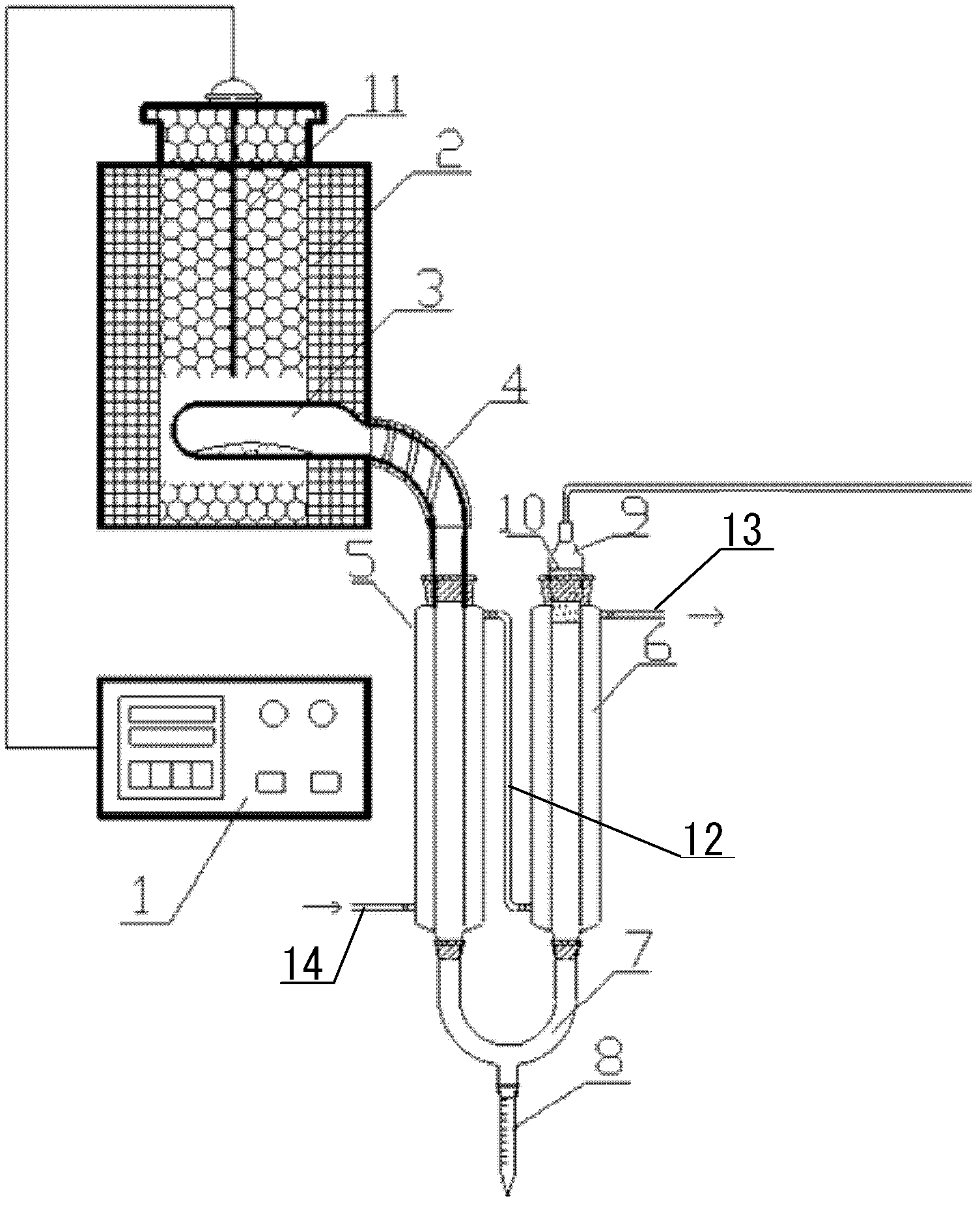
[0031] use figure 1 The shown carbonization system of the present invention performs low-temperature carbonization on lignite (I) whose industrial analysis and elemental analysis are shown in Tables 1 and 2 below. The benchmarks for industrial analysis and elemental analysis are both air-dry bases, while elemental analysis is only for organic matter, excluding ash and moisture.

[0032] Table 1

[0033]

[0034] Table 2

[0035]

[0036] Power on in advance to heat the retort furnace (2) to 300°C, air-dry and pulverize 20 grams of coal samples of 0.2 mm into the dried and emptied pyrolysis chamber (3), and place the pyrolysis chamber (3) Move into the dry distillation furnace (2), and communicate with the recovery device in an airtight manner.

[0037] The technical parameters and operating conditions of the above dry distillation are as follows: initial temperature: 300°C; heating rate: 5°C / min; final temperature: 600°C, constant temperature time at the final temper...

Embodiment 2

[0048] use figure 1 The carbonization system of the present invention shown performs low temperature carbonization of lignite (II) whose industrial analysis and elemental analysis are shown in Table 4 and Table 5 below. The benchmarks for industrial analysis and elemental analysis are both air-dry bases, while elemental analysis is only for organic matter, excluding ash and moisture.

[0049] Table 4

[0050]

[0051] table 5

[0052]

[0053] Air-dried and pulverized to 0.2mm coal sample 20 grams into the dried and emptied pyrolysis chamber (3), move the pyrolysis chamber (3) into the carbonization furnace (2), and communicate with the recovery device .

[0054] The technical parameters and operating conditions of the above-mentioned dry distillation are as follows: the temperature is raised to 260° C. within 15 to 20 minutes, then the temperature is raised to 510° C. at a rate of 5° C. / min, then kept at a constant temperature for 20 minutes, and the heating is stop...


PUM


Abstract

The invention provides a carbonaceous material destructive distillation system which comprises a pyrolysis chamber for pyrolyzing a carbonaceous material, a heating temperature control device of the pyrolysis chamber, a recycling device for recycling gaseous and liquid pyrolysis products, and an exporting channel for exporting the gaseous pyrolysis products out of the pyrolysis chamber, wherein the exporting channel outwards and downwards bends and extends from the pyrolysis chamber and is communicated with the recycling device, and the inner diameter and / or bent radian of the exporting channel is large enough to ensure that the gaseous pyrolysis products formed in the pyrolysis chamber rapidly and smoothly pass through the exporting channel to leave the pyrolysis chamber and enter the recycling device. According to the carbonaceous material destructive distillation system, secondary cracking of condensable initial pyrolysis products is greatly reduced, and therefore the yield of the liquid pyrolysis products is greatly increased.

Description

technical field [0001] The invention relates to a carbonaceous material dry distillation system, in particular to a small-scale or experimental carbonaceous material pyrolysis or dry distillation system including a gaseous and liquid pyrolysis product collection device. Background technique [0002] The current small-scale or experimental coal low-temperature carbonization devices and methods mainly include the "Test Method for Gejin Low-temperature Carbonization of Coal" stipulated in the national standard GB / T 1341-2007 and the "Low-temperature Aluminum Retort of Coal" specified in GB / T 480-2000. Dry distillation test method". However, the above two low-temperature dry distillation devices and methods have the following deficiencies. [0003] The dry distillation device used in the "Gejin low temperature dry distillation test method of coal" stipulated in the national standard GB / T 1341-2007 is figure 2 The dry distillation tube shown, the experimental method is as follo...

Claims


Application Information

Patent Timeline
Patent Type & Authority Patents(China)
IPC IPC(8): C10B15/00C10B29/00C10B27/00C10B53/00C10B53/02C10B53/04C10B53/06C10B53/07C10B55/00C10B57/00C10G1/00C10G1/10
CPCY02E50/14Y02E50/10Y02P20/143
Inventor 张永发郭小汾李香兰徐英王理丁嘉丽
Owner CHNA ENERGY INVESTMENT CORP LTD
Why Eureka
Try Eureka