
Automatic switch

A technology of automatic switch and normally open relay, which is applied in the direction of engine components, machines/engines, mechanical equipment, etc., can solve problems such as wear and tear, and achieve the effects of reducing working pressure, idling fuel consumption and exhaust emissions

Inactive Publication Date: 2013-03-06
莫嘉林
View PDF2 Cites 0 Cited by
  • Summary
  • Abstract
  • Description
  • Claims
  • Application Information

AI Technical Summary

Problems solved by technology

[0002] At present, in the known exhaust gas turbocharger, after the engine stops, the internal rotor immediately rotates at a high speed in the state of lack of oil supply, so that most of the wear of the rotor bearing occurs at this time. If the engine is running at high speed When immediately shut down, the wear is even greater

Method used


Image

  • Automatic switch

Examples


Embodiment Construction

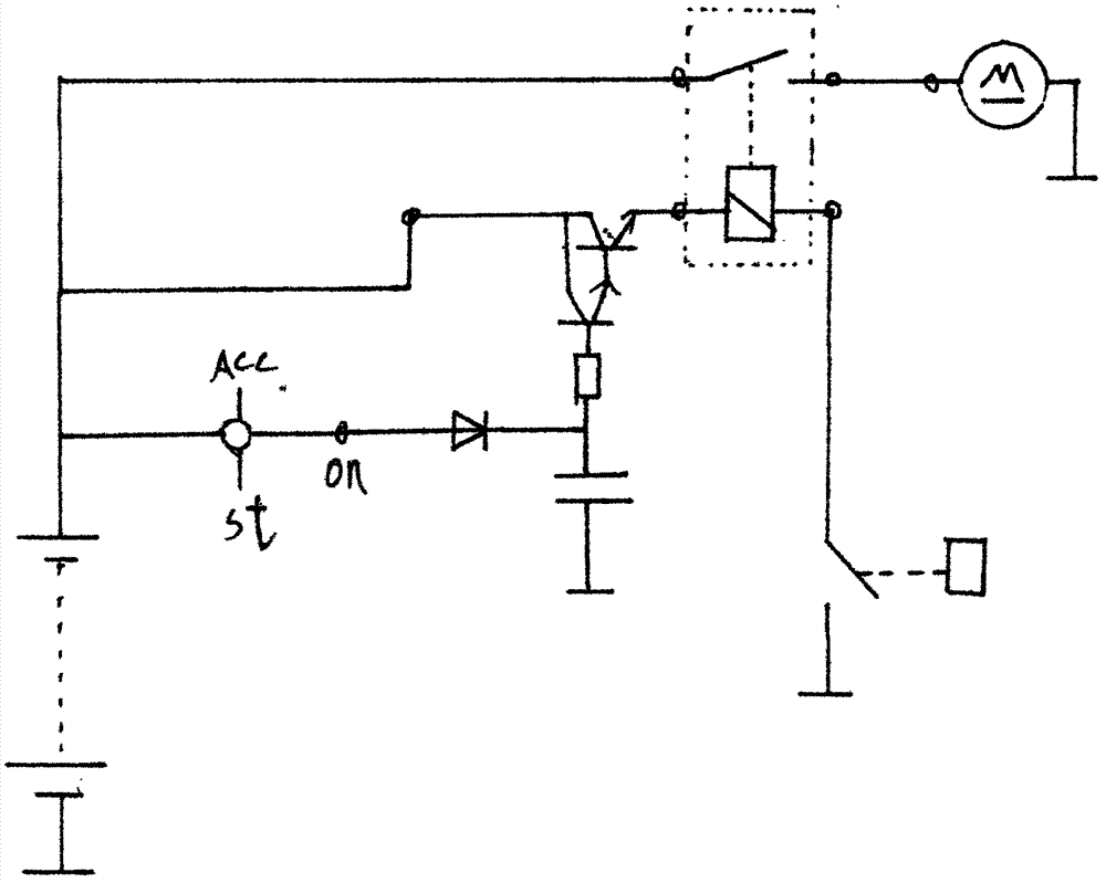
[0013] figure 1 Among them, the on terminal of the ignition switch (1) is connected to the cathode of the diode (2), the anode of the diode (2) is connected to the anode of the capacitor (3) and one end of the resistor (4), the cathode of the capacitor (3) is grounded, and the resistor The other end of (4) is connected to the base of the high-power tube (5), the collector of the high-power tube (5) is connected to the positive pole of the power supply, the emitter is connected to one end of the coil of the normally open relay (6), and the normally open relay (6) ) The other end of the coil is connected to the terminal of the oil pressure alarm (7), and one end of the contact of the normally open relay (6) is connected to the positive pole of the power supply, and the other end is connected to the positive pole of the oil pump motor (8).


PUM


Abstract

An automatic switch can control an electric oil pump to supply engine oil to a waste gas turbocharger within a certain period of time before starting of an engine and after stopping of the engine so as to protect a rotor bearing of the waste gas turbocharger and prevent the rotor bearing to run in an oil shortage state. Idling oil consumption and waste gas emission lasting for several minutes can be reduced when in each stop of the waste gas turbocharged engine.

Description

Technical field [0001] The invention relates to an automatic switch, which can control an electric oil pump to pump oil needed for lubrication and cooling to an exhaust gas turbocharger within a set period of time before the engine starts and after the engine stops. Background technique [0002] At present, in the known exhaust gas turbocharger, after the engine is stopped, the internal rotor immediately rotates at a high speed in the state of lack of oil supply, so that most of the wear of the rotor bearing occurs at this time. If the engine is running at high speed When it is shut down immediately, the wear is even worse. Therefore, regarding the use of exhaust gas turbocharger engine, it is recommended to idle for a few minutes before shutting down the engine. The purpose is to make the rotor inside the exhaust gas turbocharger reduce the speed of the rotor to Minimum, so that after the engine is shut down, the rotor bearings wear as relatively as possible without oil fo...

Claims


Application Information

Patent Timeline
IPC IPC(8): F02B39/14
Inventor 莫嘉林
Owner 莫嘉林
Learn More