
Box body of railway vehicle traveling gearbox

A technology for rail vehicles and gearboxes, which is applied to belts/chains/gears, transmission boxes, components with teeth, etc., and can solve problems such as unbalanced internal and external pressure differences, leakage, and limited operating space

Active Publication Date: 2013-03-06
CHANGZHOU RUITAI ENG MASCH CO LTD +1
View PDF6 Cites 9 Cited by
  • Summary
  • Abstract
  • Description
  • Claims
  • Application Information

AI Technical Summary

Problems solved by technology

In this technical solution, the joint surface is arranged obliquely, and the bearing seat of the input shaft is located in the lower box as a whole, which reserves a certain space for the arrangement of the torsion bar to a certain extent, but the torsion bar must adopt a curved shape, and the gearbox is simultaneously supported by the shaft. Combined force of pulling and torsion in the vertical and vertical directions, the force on the box is enlarged, and the connecting screw between the torsion bar and the box is subjected to shear stress. During high-speed operation, the reliability of hoisting is greatly reduced due to the large vibration impact; On the side of the box, on the one hand, it makes the casting and processing of the box difficult, and also affects the overall rigidity of the box to a certain extent; because there is no vent hole on the box, the pressure difference between the inside and outside cannot be balanced, which brings great harm to the design of the sealing mechanism. It is difficult to install, and at high speed, it is easy to leak; the position of the oil injection port is low and flat, and it is close to the connection parting surface, the operating space is limited, and it is difficult to inject oil

Method used


Image

  • Box body of railway vehicle traveling gearbox
  • Box body of railway vehicle traveling gearbox
  • Box body of railway vehicle traveling gearbox

Examples


Embodiment Construction

[0019] The present invention is described in further detail below in conjunction with the embodiment that accompanying drawing provides.

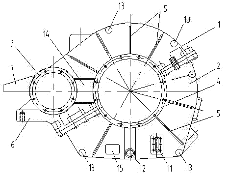
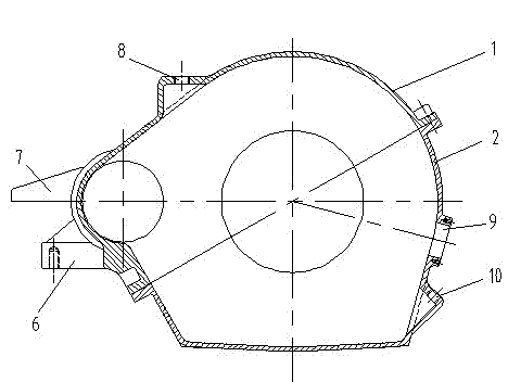
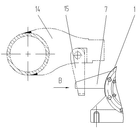
[0020] Such as figure 1 , 2 As shown, a rail vehicle running gear box body includes an upper box body 1 and a lower box body 2, the upper box body 1 and the lower box body 2 are fixedly connected to form a box body, and the box body has an input shaft bearing seat 3 and an axle shaft The bearing seat 4, the axle bearing seat 4 is a split structure, half of which is located on the upper box body 1, and the other half is located on the lower box body 2, and the joint surface between the upper box body 1 and the lower box body 2 is Arranged obliquely, the upper box body 1 and the lower box body 2 are distributed with several reinforcing ribs 5 on the surface, and the reinforcing ribs 5 extend outward from the periphery of the axle bearing seat 4, and the input shaft bearing seat 3 is located on the upper box body 1 as a whole , the end of th...


PUM


Abstract

The invention discloses a box body of a railway vehicle traveling gearbox. The box body comprises an upper box body and a lower box body, wherein the upper and lower box bodies are fixedly connected to form the box body; an input shaft bearing pedestal and an axle bearing pedestal are arranged in the box body; the axle bearing pedestal is of a split structure, one half is located on the upper box body and the other half is located on the lower box body; the combination surface between the upper and lower box bodies is inclined; a plurality of reinforcement ribs are distributed on the surfaces of the upper and lower box bodies; the reinforcement ribs extend outwards from the periphery of the axle bearing pedestal; the input shaft bearing pedestal is integrally located on the upper box body; the end of the combination surface between the upper and lower box bodies close to the input shaft bearing pedestal is lower than the end close to the axle bearing pedestal; the included angle between the combination surface and the horizontal direction is ranged in 25-35 degrees; a torsion bar connection boss is arranged at the lower part of the end of the upper box body close to the input shaft bearing pedestal; and a safety support is arranged at the upper part of the end of the upper box body close to the input shaft bearing pedestal. The box body of the railway vehicle traveling gearbox is simple and reasonable in structure, safe, reliable and capable of satisfying the high-speed traveling requirement.

Description

technical field [0001] The invention relates to a rail vehicle running gear box, and belongs to the technical field of traction gear drive devices for railway vehicles. Background technique [0002] At present, although my country's rail car product industry has formed a production and scientific research system with a certain production capacity and technical level, the maximum driving speed is basically around 100km / h, and a few can reach 120km / h. In today's line transportation capacity is becoming more and more concentrated, and the operation speed is getting faster and faster, this kind of product will inevitably affect the operation efficiency of the line to a certain extent, especially cannot meet the requirements of passenger dedicated lines. [0003] In the Chinese Patent Publication No.: CN201666353U, in the patent literature titled "A Gearbox Case for Rail Transit Vehicles", a gearbox case for rail transit vehicles is introduced, which is characterized by: box The...

Claims


Application Information

Patent Timeline
Patent Type & Authority Applications(China)
IPC IPC(8): F16H57/02F16H57/021F16H57/03F16H57/027
Inventor 陈亚东胡高华
Owner CHANGZHOU RUITAI ENG MASCH CO LTD
Learn More