Method for synchronously obtaining electric signals of any two ends of power transmission line

A transmission line, synchronous acquisition technology, applied in the direction of measuring current/voltage, measuring electricity, measuring electrical variables, etc., can solve the problem of increasing equipment costs

Active Publication Date: 2013-03-06
CHONGQING UNIV +2
View PDF5 Cites 9 Cited by
  • Summary
  • Abstract
  • Description
  • Claims
  • Application Information

AI Technical Summary

Problems solved by technology

The method based on the GPS satellite clock not only increases the cost of equipment, but also has security and controllability factors in the GPS satellite clock. The time synchronization of electrical signal collection at both ends of the transmission line should not be completely dependent on the satellite clock reference

Method used


Image

  • Method for synchronously obtaining electric signals of any two ends of power transmission line
  • Method for synchronously obtaining electric signals of any two ends of power transmission line
  • Method for synchronously obtaining electric signals of any two ends of power transmission line

Examples


Embodiment Construction

[0052] The present invention will be further described below in conjunction with accompanying drawing:

[0053] The present invention comprises the following steps:

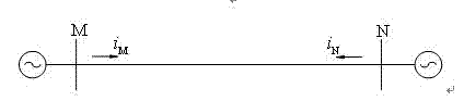
[0054] (1) Collect electrical signals at the beginning and end of the transmission line

[0055] Use the signal collector to collect the voltage and current signal u at the head end of the transmission line at time t in real time M (t), i M (t) paired sequence value; use the signal collector to collect the voltage and current signal u at the end of the transmission line at the time t' in real time N (t'), i N (t’) paired sequence values, the time interval for collecting electrical signals is T s , and 10 -6 s≤T s ≤10 -2 s;

[0056] (2) Calculate the current value i at the end of the transmission line Nj (t)

[0057] ①. Calculate the voltage function expression u at the head end of the transmission line M (t) and current function expression i M (t);

[0058] Two adjacent voltage signals u at the head ...


PUM


Abstract

The invention provides a method for synchronously obtaining electric signals of any two ends of a power transmission line. The method comprises the following steps of: collecting electric signals uM(t), iM(t), uN(t') and iN(t') of head and tail ports of the power transmission line; calculating a current calculation value iNj(t) of the tail end of the power transmission line at a t moment by voltage and current collection sequences uM(t) and iM(t) at the front end of the power transmission line according to a power transmission line distribution parameter circuit model; calculating a collection time deviation (t-t') of the two ends of the power transmission line according to the current calculation value iNj(t) of the tail end of the power transmission line at the t moment and a collection current sequence iN(t') of the tail end of the power transmission line at a t' moment; and judging whether a collection moment t' of the tail end of the power transmission line is adjusted or not by comparing with a collection time deviation adjusting setting value delta tset. Circularly, the synchronous collection of the electric signals of any two ends of the power transmission line is realized. The method disclosed by the invention eliminates the influences of inconsistency of transmission delay of a data channel of the power transmission line on synchronous collection of the electric signals; and a time block standard signal except for an electric power system does not need to be introduced so that the microsecond-grade synchronous collection precision of the power transmission line can be realized.

Description

(1) Technical field [0001] The invention relates to a method for synchronously collecting electrical signals at both ends of a transmission line in a power system, which is suitable for applications requiring synchronous collection of electrical signal data at both ends of the transmission line. (two), background technology [0002] Transmission line is an important component in the power system, and its safe operation plays an extremely important role in the stability of the power system. During the operation of the power system, transient or permanent faults will occur on the transmission line, and the occurrence of these faults will have a great impact on the operation of the power system, especially in the ultra (ultra) The exit of line faults brings great disturbance to the operation of the system, and in some cases of heavy load operation, it may even cause cascading failures, causing multiple lines to trip and exit or even disconnect the power grid, causing huge losse...

Claims


Application Information

Patent Timeline
Patent Type & Authority Applications(China)
IPC IPC(8): G01R31/02G01R31/08G01R19/28
Inventor 何建军罗建徐瑞林陈涛朱特张晓勇高晋张友强蒋昆钟加勇刘祖建李杰王瑞妙王洪彬樊俊言任成君王一夫张开迪
Owner CHONGQING UNIV
Why Eureka
Try Eureka