Laser night vision integral high-speed camera with cloud deck and monitoring method thereof

A PTZ camera and laser night vision technology, applied in television, optics, photography, etc., can solve the problems of short monitoring distance, large equipment volume, and small volume, and achieve the effect of high power and small volume

Active Publication Date: 2013-03-06
深圳市安星数字系统有限公司
View PDF9 Cites 17 Cited by
  • Summary
  • Abstract
  • Description
  • Claims
  • Application Information

AI Technical Summary

Problems solved by technology

[0003] One method is to install searchlights for lighting, and its disadvantages are: no concealment, large equipment volume, low electro-optic efficiency, and insufficient distance
[0004] Another method is to install an infrared illuminator. The disadvantages are: short life, difficult to adjust the irradiation angle, and short monitoring distance.
However, under the premise that the overall volume of the equipment is greatly reduced and the heat dissipation area is simultaneously reduced, this technical solution still adopts the t

Method used


Image

  • Laser night vision integral high-speed camera with cloud deck and monitoring method thereof
  • Laser night vision integral high-speed camera with cloud deck and monitoring method thereof
  • Laser night vision integral high-speed camera with cloud deck and monitoring method thereof

Examples


Embodiment 1

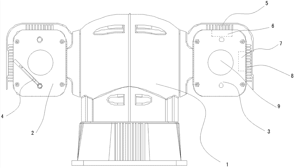
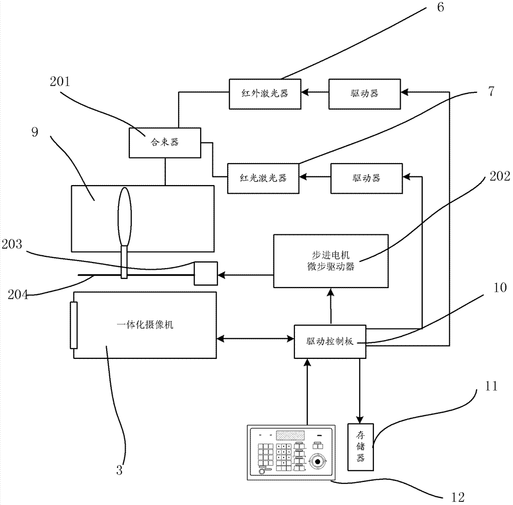
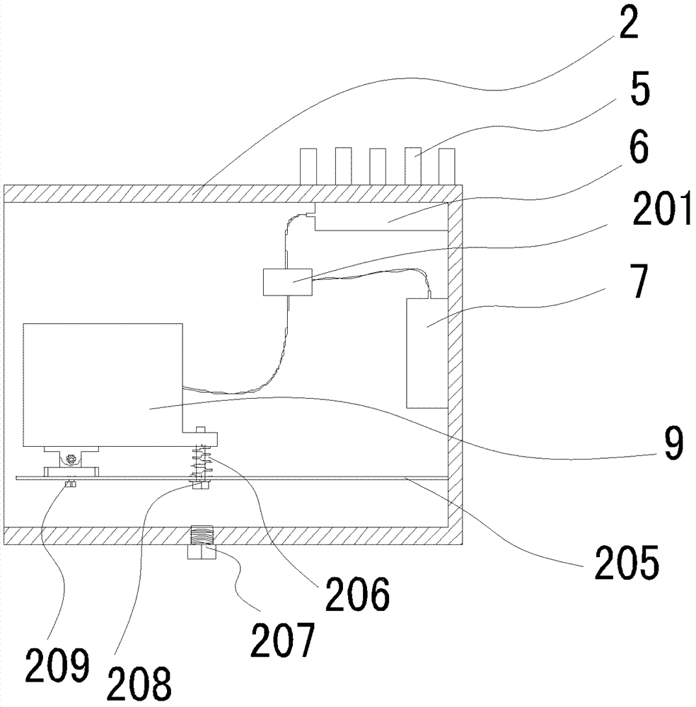
[0032] Such as figure 1 , figure 2 , image 3 and Figure 4, a laser night vision integrated high-speed pan-tilt camera, including a semiconductor laser 2 and an integrated camera 3 respectively installed on the high-speed pan-tilt 1, an optical zoom mirror 9 is installed on the front end of the semiconductor laser 2 shell, and a semiconductor laser 2 is provided with a A semiconductor infrared laser generator 6 and a red laser generator 7, a large-sized upper cooling fin 5 and a large-sized side cooling fin 8 are arranged outside the casing of the semiconductor laser 2, and the semiconductor infrared laser generator 6 is in thermal contact with the upper cooling fin 5 , the red laser generator 7 is in thermal contact with the side heat sink 8, the semiconductor infrared laser generator 6 and the red laser generator 7 are connected to the optical zoom mirror 9 through a beam combiner 201 optical fiber, the semiconductor infrared laser generator 6 and the red laser generator...

Embodiment 2

[0039] Such as Figure 5 The difference from Embodiment 1 is that the semiconductor infrared laser generator 6 is provided with a temperature sensor 13 electrically connected to the driving control board 10 . It is used to monitor the heating state of the semiconductor laser generator.

[0040] Its monitoring step (3) is, the pulse work is: after the synchronous zoom is determined, the drive control board 10 controls the semiconductor infrared laser generator 6 at regular intervals according to the information fed back by the temperature sensor 13 arranged on the semiconductor infrared laser generator 6 It works synchronously with the integrated camera 3, and if the temperature is too high, it stops working and sends an alarm to the remotely connected server.

[0041] It is particularly proposed that the command input can be an external setting keyboard 12, or a server connected through a communication interface.


PUM


Abstract

The invention relates to monitoring equipment and discloses a laser night vision integral high-speed camera with a cloud deck which is characterized in that a stepping motor electrically connected with a drive control panel is mounted on the cloud deck. An optical zoom lens is horizontally driven by the stepping motor through a screw rod. An interface electrically connected with the integral camera is arranged on the drive control panel. A storage is disposed on the drive control panel. A semiconductor laser generator is mounted in a shell of a semiconductor laser unit and mounted on radiating fins outside the shell of the semiconductor laser unit by means of thermal conduction. The invention further discloses a monitoring method of the laser night vision integral high-speed camera. The monitoring method includes the steps of firstly, building a database list; secondly, zooming synchronously; and thirdly pulse operation. Lighting angle of laser projection can automatically follow viewing angle of the camera, pulse operation is combined with direct radiation, and accordingly normal operation can be guaranteed while size power ration is smaller. In addition, the laser night vision integral high-speed camera with the cloud deck can shoot plate number and externally adjust light spots.

Description

technical field [0001] The invention relates to monitoring equipment, in particular to an economical, efficient, convenient and easy-to-use laser night vision integrated high-speed pan-tilt camera and a monitoring method thereof, which can realize monitoring within a range of 1 kilometer regardless of day or night. Background technique [0002] With the increasing popularity of surveillance systems in commercial and civilian use, surveillance cameras are widely used in various fields to protect social security. Video surveillance cameras are widely used in residential buildings, real estate villas, shopping malls, and financial offices. And it is growing at a rate of tens of thousands every day. Different application fields require different types of surveillance cameras. In a considerable number of outdoor applications, it is usually required that the cameras can monitor day and night and the monitoring distance can reach hundreds of meters to 1 kilometer. However, the app...

Claims


Application Information

Patent Timeline
IPC IPC(8): G03B15/05G03B17/55H04N5/232H04N7/18
Inventor 丁新生
Owner 深圳市安星数字系统有限公司
Why Eureka
Try Eureka