Plug-in touch module and touch display device

A touch module, plug-in technology, applied in the direction of instrument, electrical digital data processing, data processing input/output process, etc., can solve the problem of increased battery power consumption, reduce power consumption, save production costs, reduce The effect of electromagnetic signal strength

Active Publication Date: 2013-03-06
BEIJING BOE OPTOELECTRONCIS TECH CO LTD
View PDF5 Cites 61 Cited by
  • Summary
  • Abstract
  • Description
  • Claims
  • Application Information

AI Technical Summary

Problems solved by technology

[0004] Because the metal wires of the electromagnetic touch antenna board are non-transparent, and the thickness of the whole electromagnetic touch antenna board is relatively thick, it can only be attached to the rear side of the display panel generally, and the touch module with a back-mounted structure During the touch process, there is a display panel between the electromagnetic pen and the antenna board. In order to achieve smooth touch, it is necessary to increase the electromagnetic signal strength of the electromagnetic pen, which will also increase the power consumption of the battery, and increase the strength of the electromagnetic signal. It will also have a certain impact on the display panel

Method used


Image

  • Plug-in touch module and touch display device
  • Plug-in touch module and touch display device
  • Plug-in touch module and touch display device

Examples


Embodiment Construction

[0017] The specific implementation manners of the plug-in touch module and the touch display device provided by the embodiments of the present invention will be described in detail below with reference to the accompanying drawings.

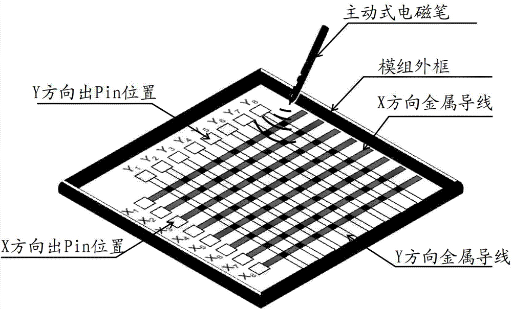
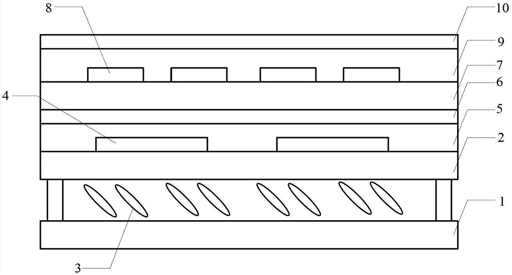
[0018] The embodiment of the present invention provides a plug-in touch module, which adds electromagnetic touch electrodes to the structure of the existing projected capacitive touch module to realize the combination of electromagnetic touch and capacitive touch. The existing projected capacitive touch module specifically includes: capacitive touch sensing electrodes, capacitive touch driving electrodes that are insulated from the capacitive touch sensing electrodes and placed across them, and metal bridges that bridge adjacent capacitive touch driving electrodes , in the structure of the projected capacitive touch module, the present invention also adds the following components:

[0019] a first electromagnetic touch electrode that is insulated ...


PUM


Abstract

The invention discloses a plug-in touch module and a touch display device. A capacitive touch function can be realized through capacitive touch induction electrodes, capacitive touch driving electrodes and a metal bridge bridged over the adjacent capacitive touch driving electrode, wherein the capacitive touch driving electrodes and the capacitive touch induction electrodes are insulated and are crosswise arranged; meanwhile, an electromagnetic touch function can be realized through a first electromagnetic touch electrode and a second electromagnetic touch electrode; the first electromagnetic touch electrode is insulated with the metal bridge and is arranged on the same layer as the metal bridge; and the second electromagnetic touch electrode and the first electromagnetic touch electrode are insulated and are crosswise arranged. Since the electromagnetic touch electrodes are prearranged, the intensity of an electromagnetic signal of an electromagnetic pen can be reduced, thereby reducing the power consumption and reducing the influence of an electromagnetic signal on a display panel; and since the first electromagnetic touch electrode and the metal bridge bridged over the capacitive touch driving electrode are arranged on the same layer, the thickness of the entire module can be reduced while the combination of electromagnetic induction and capacitive touch is realized, and meanwhile, the production cost of the entire module is also saved.

Description

technical field [0001] The present invention relates to the field of touch technology, in particular to an external touch module and a touch display device Background technique [0002] With the rapid development of display technology, touch screen panels (Touch Screen Panels) have gradually spread throughout people's lives. At present, touch screens can be divided into: resistive, capacitive, infrared, surface acoustic wave, electromagnetic, vibration induction, and frustrated total internal reflection optical induction, etc. according to their working principles. Among them, the capacitive touch screen is sought after by the industry as a new favorite due to its unique touch principle, high sensitivity, long life, high light transmittance and other advantages. The electromagnetic touch panel is widely used in many high-level computer aided drawing (CAD, Computer Aided Design) systems, such as AutoCAD, because it can realize the characteristics of original handwriting. ...

Claims


Application Information

Patent Timeline
Patent Type & Authority Applications(China)
IPC IPC(8): G06F3/044G06F3/046
Inventor 杨盛际王海生刘英明程凌志王春雷
Owner BEIJING BOE OPTOELECTRONCIS TECH CO LTD
Why Eureka
Try Eureka