
Chip packaging method and chip packaging structure

A chip packaging structure and chip packaging technology, applied in the direction of radiation control devices, etc., can solve problems such as inability to perform imaging functions, and achieve the effects of saving space, reducing packaging costs, and reliable working conditions

Active Publication Date: 2013-03-06
YANTAI RAYTRON TECH
View PDF5 Cites 6 Cited by
  • Summary
  • Abstract
  • Description
  • Claims
  • Application Information

AI Technical Summary

Problems solved by technology

Infrared focal plane detector manufacturing technology is the core of thermal imaging technology, and infrared focal plane array detector chip sealing packaging technology is the key link to realize infrared detector imaging. Infrared focal plane array detector chip needs to be in a sealed environment under vacuum work in the middle, otherwise the imaging function of its bolometer cannot be exerted

Method used


Image

  • Chip packaging method and chip packaging structure
  • Chip packaging method and chip packaging structure
  • Chip packaging method and chip packaging structure

Examples


Embodiment Construction

[0043] The principles and features of the present invention are described below in conjunction with the accompanying drawings, and the examples given are only used to explain the present invention, and are not intended to limit the scope of the present invention.

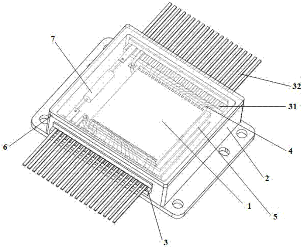
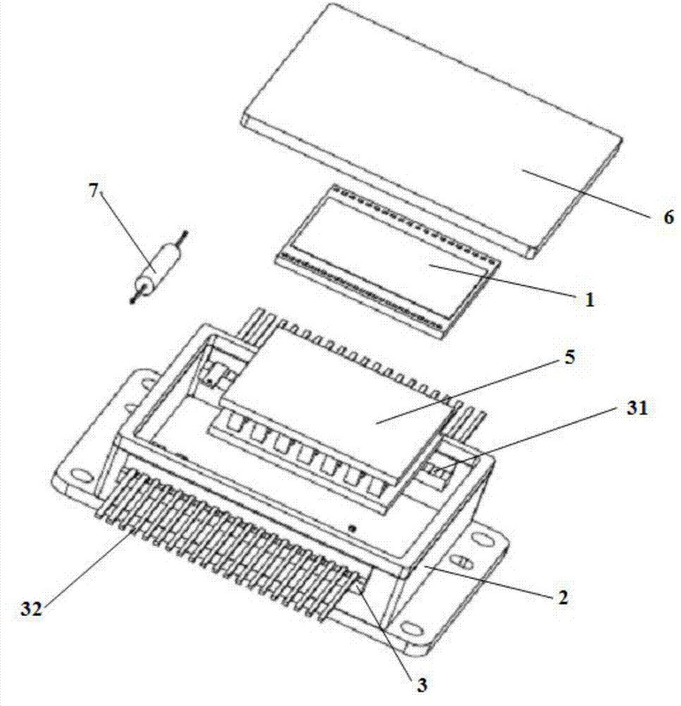
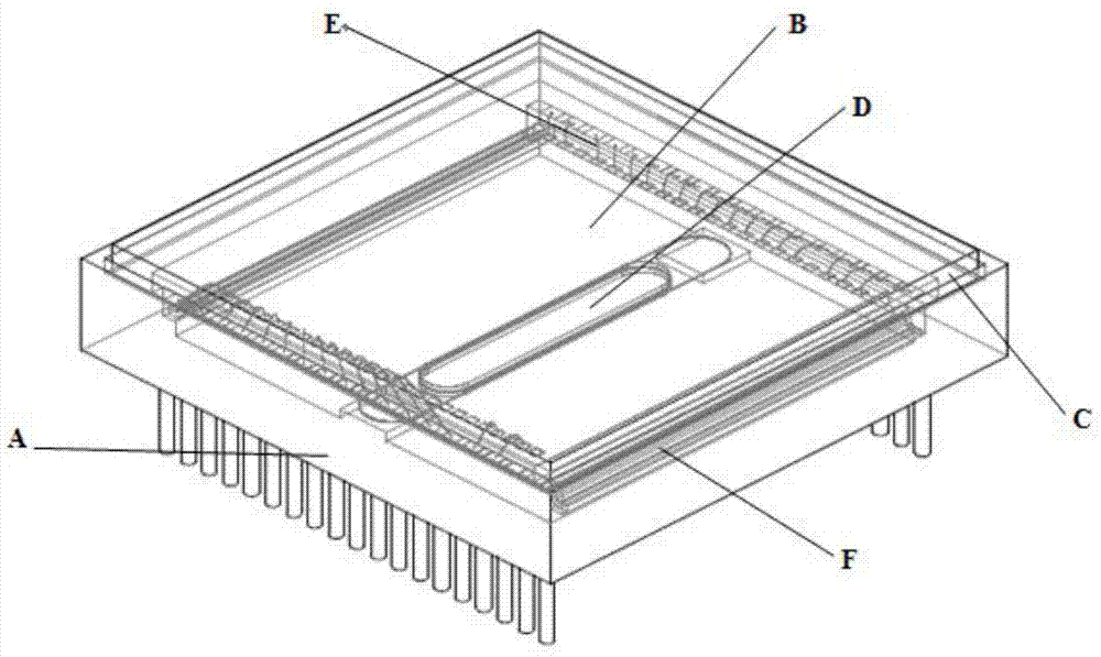
[0044] A kind of chip packaging method of the present invention, the steps are as follows: Figure 5 As shown, prepare a package case A, make the package case a rectangular cavity with an open top, make a step-type welding area A4 inside the opening of the package case, and make a step-type welding area A4 on both sides of the step-type welding area A4 A step A1 is made on the inner wall, pads A3 are installed on the inner walls of the other two sides of the step-shaped welding area A4, and the height of the pad A3 is greater than the height of the step, and the metal pin A5 located outside the package shell is connected to the pad A3 is electrically connected; two metal platforms A2 are installed on the inner botto...


PUM


Abstract

The invention relates to a chip packaging method, which comprises the following steps of: step 1, connecting a buffer substrate, a chip and a packaging shell into a whole body; and step 2, connecting an optical window and the structure formed in the step 1 into a sealed cavity in a sealing manner. The invention also relates to a chip packaging structure, which comprises the chip, the optical window, the packaging shell and the buffer substrate, wherein the packaging shell and the optical window form the sealed cavity, the buffer substrate is located in the sealed cavity, the chip is arranged on the upper surface of the buffer substrate, the lower surface of the buffer substrate is provided with a thin film getter, and a gap is formed between the buffer substrate and the inner wall of the packaging shell. By the chip packaging method and the chip packaging structure, disclosed by the invention, the chip packaging structure has mechanical shock resisting capability, so that the vacuum environment required by the chip can be realized, the packaging size can be reduced, and the packaging cost can be reduced.

Description

technical field [0001] The invention relates to a semiconductor packaging technology, in particular to a chip vacuum packaging technology. Background technique [0002] Infrared imaging technology is more and more widely used in industrial sensing, image monitoring, automobile industry, fire search and rescue, and even military navigation and night vision. Infrared focal plane detector manufacturing technology is the core of thermal imaging technology, and infrared focal plane array detector chip sealing packaging technology is the key link to realize infrared detector imaging. Infrared focal plane array detector chip needs to be in a sealed environment under vacuum Otherwise, the imaging function of its bolometer cannot be exerted. [0003] Generally speaking, the high-vacuum packaging technology of infrared focal plane array detectors uses a metal shell as a sealed cavity, and its typical structure is as follows: figure 1 with figure 2 As shown, the housing 2 is an ope...

Claims


Application Information

Patent Timeline
Patent Type & Authority Applications(China)
IPC IPC(8): H01L27/146
Inventor 熊笔锋马宏王宏臣江斌
Owner YANTAI RAYTRON TECH
Learn More