Card edge connector

A technology of card edge connectors and contact parts, applied in the direction of connection, contact parts, base/housing, etc., which can solve the problems of reduced elastic holding force, increased thickness, unreliable electrical contact, etc.

Inactive Publication Date: 2013-03-06
TYCO ELECTRONICS (SHANGHAI) CO LTD
View PDF6 Cites 5 Cited by
  • Summary
  • Abstract
  • Description
  • Claims
  • Application Information

AI Technical Summary

Problems solved by technology

Although the elastic parts 102', 202' with greater flexibility will facilitate the insertion operation of the memory stick, but when the elastic parts 102', 202' have greater flexibility, when the deformation of the elastic parts 102', 202' is the same In this case, the elastic holding force applied by the elastic parts 102', 202' to the memory stick will be reduced, which will lead to unreliable electrical contact between the contact parts of the terminals 10', 20' and the memory stick.
Therefore, in order to ensure that the elastic parts ...

Method used


Image

  • Card edge connector
  • Card edge connector
  • Card edge connector

Examples


Embodiment Construction

[0040] The technical solutions of the present invention will be further specifically described below through the embodiments and in conjunction with the accompanying drawings. In the specification, the same or similar reference numerals designate the same or similar components. The following description of the embodiments of the present invention with reference to the accompanying drawings is intended to explain the general inventive concept of the present invention, but should not be construed as a limitation of the present invention.

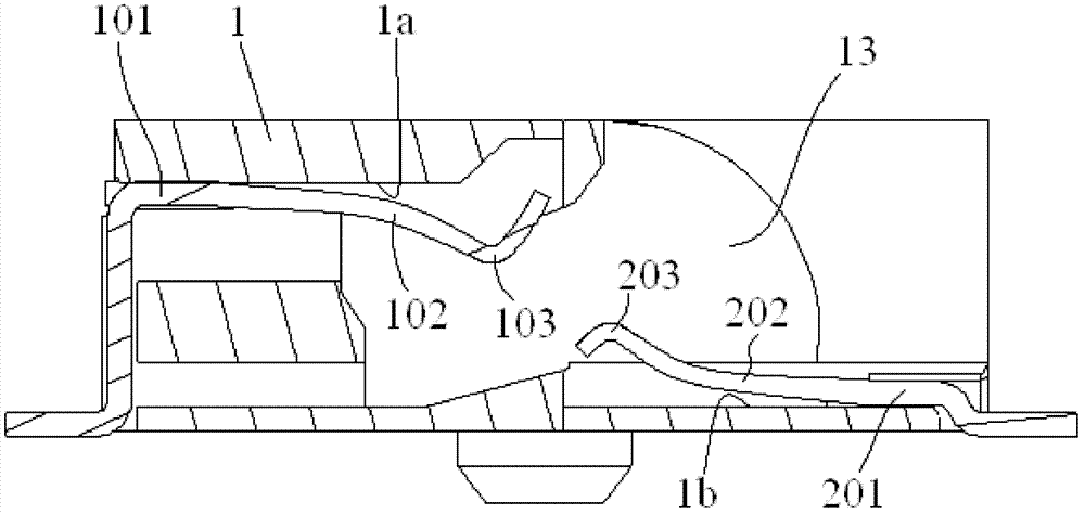
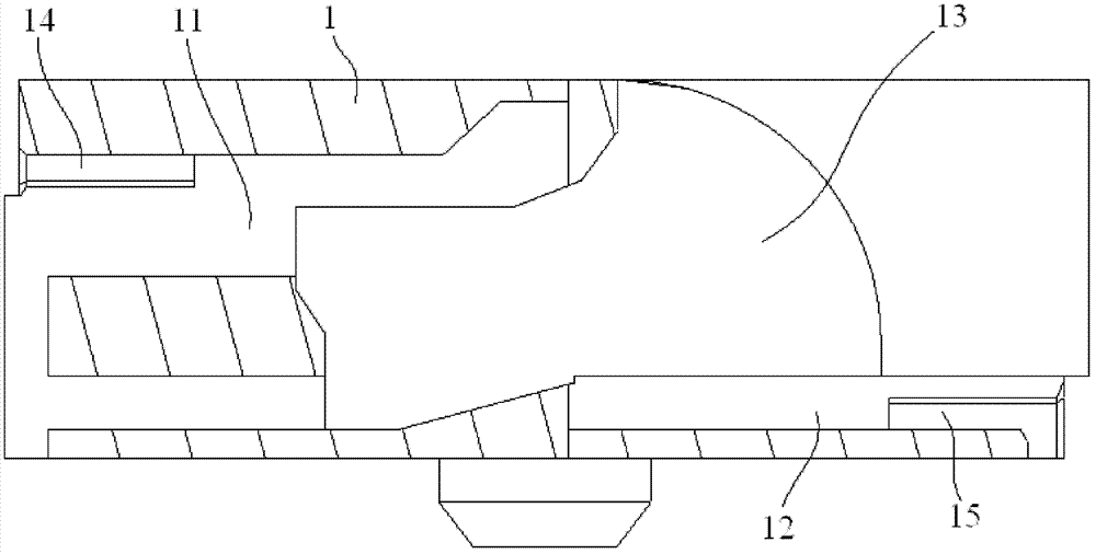
[0041] figure 2 A three-dimensional schematic diagram of a double-row pin card edge connector according to an embodiment of the present invention is shown.

[0042] When using, figure 2 The shown dual-row pin card edge connector is placed horizontally on a circuit board (not shown), such as the motherboard of a notebook computer, so that the thickness of the notebook computer can be reduced.

[0043] Such as figure 2 As shown, the doubl...


PUM

PropertyMeasurementUnit
Thicknessaaaaaaaaaa

Abstract

The invention discloses a card edge connector which comprises a body, a first terminal and a second terminal. The body is provided with an insert slot. The first terminal is accommodated in a terminal slot on the upper side wall of the insert slot, and the second terminal is accommodated in a terminal slot on the lower side wall of the insert slot. An elastic portion of the second terminal comprises at least one bending joint, the bending joints do not contact with the inner wall of the body before an electronic card module is inserted into the insert slot. After the electronic card module is inserted into the insert slot, the elastic portion of the second terminal deforms elastically so that the bending joints are butted against the inner wall of the body and serve as supporting points of the elastic portion. The arm of force of the elastic portion is decreased gradually in the process of inserting the electronic card module, particularly, the arm of force of the elastic portion is maximum at the beginning of inserting the electronic card module so that the elastic portion has enough flexibility and brings convenience to insertion of an internal memory chip, but is changed to be minimum when the electronic card module is inserted completely so that the flexibility of the elastic portion is weakened, rigidity thereof is enhanced, and elastic holding capacity to the electronic card module is enhanced.

Description

technical field [0001] The invention relates to a card edge connector, in particular to a small-thickness double-row pin card edge connector (SO-DIMM, Small Outline Dual Inline Memory Module). Background technique [0002] Figure 1a A schematic structural view showing the first terminal 10' of an existing double-row pin card edge connector; and Figure 1b A schematic structural diagram of a second terminal 20' of an existing double-row pin card edge connector is shown. [0003] Such as Figure 1a As shown, before and after the memory stick (not shown) is inserted into the electronic card module slot 13', the first elastic part 102' of the first terminal 10' is always suspended on the body 1 of the double-row card edge connector The first terminal slots 11' and 13' of ' are not in contact with the inner wall of the main body 1', therefore, during the process of inserting the memory stick, the fulcrum O1' of the first terminal 10' remains unchanged, as Figure 1a As shown, t...

Claims


Application Information

Patent Timeline
IPC IPC(8): H01R12/73H01R13/02H01R13/20H01R13/46
Inventor 雷云王建新张镒纬汪云河
Owner TYCO ELECTRONICS (SHANGHAI) CO LTD
Why Eureka
Try Eureka