Uninterrupted power supply (UPS) battery low voltage discharge protection circuit with return difference

A low-voltage discharge and protection circuit technology, which is applied in the direction of emergency protection circuit devices, electrical components, etc., can solve the problems of increasing UPS power failure points, failure to protect batteries, and high cost of contactors

Active Publication Date: 2015-01-21
EAST GRP CO LTD
View PDF5 Cites 0 Cited by
  • Summary
  • Abstract
  • Description
  • Claims
  • Application Information

AI Technical Summary

Problems solved by technology

One way is to add a contactor at the connection end of the battery and the busbar, and disconnect the battery from the busbar when the battery is low voltage, so that the battery is in an open state to protect the battery, but the cost of the contactor is high, and the control circuit needs to be added , It also increases the failure point of UPS power supply and increases the failure rate. The new UPS power supply stops using the contactor, so it cannot effectively protect the battery when the battery is low voltage.
[0003] On the other hand, since the existing protection circuit generally adopts setting a threshold value, and controls whether the auxiliary power board works according to whether the battery voltage is greater than or lower than the threshold value, in this case, when the battery voltage fluctuates near the threshold value, the auxiliary power board will continuously If the ground is powered on and off, it will cause huge damage to the auxiliary power board and the control circuit

Method used


Image

  • Uninterrupted power supply (UPS) battery low voltage discharge protection circuit with return difference

Examples


Embodiment 1

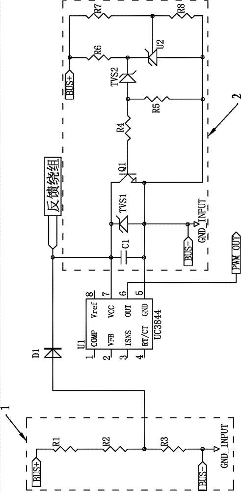
[0017] One of the specific implementations of a UPS battery low-voltage discharge protection circuit that can set a hysteresis in the present invention, such as figure 1 As shown, it includes: an auxiliary power board that takes power from the battery through the bus bar, the auxiliary power board includes a control chip U1 for controlling power supply, and also includes an input terminal connected to the bus bar and the voltage of the input terminal reaches the startup threshold V H When starting the start-up circuit 1 of the control chip U1, the input terminal is connected to the bus bar, and the voltage at the input terminal of the output terminal is lower than the blocking threshold V L When blocking the low-voltage blocking circuit 2 of the control chip U1, the startup threshold V H greater than the blockout threshold V L .

[0018] In this embodiment, the auxiliary power board takes power from the busbar under the control of the control chip UI, and the busbar takes po...

Embodiment 2

[0023] The second specific embodiment of a UPS battery low-voltage discharge protection circuit that can set hysteresis in the present invention, the main technical solution of this embodiment is the same as that of embodiment 1, and the features that are not explained in this embodiment are adopted in embodiment 1 explanation and will not be repeated here. The difference between this embodiment and Embodiment 1 is that the resistor R2 is an adjustable resistor, and the resistor R7 is also an adjustable resistor. Combining with the analysis of Example 1, it can be known that the startup threshold V can be easily changed by adjusting these two adjustable resistors. H and the blocking threshold V L , It is also convenient to adjust the hysteresis according to the needs. Certainly, the resistors R1, R3 and R8 may also be adjustable resistors, or only the resistor R2 may be set as an adjustable resistor, and only the adjustment method is changed accordingly.


PUM


Abstract

The invention relates to the field of an uninterrupted power supply (UPS) battery low voltage discharge protection, and in particular relates to a UPS battery low voltage discharge protection circuit with return difference. The UPS battery low voltage discharge protection circuit comprises a starting circuit for starting a control chip U1 of an auxiliary power supply board when an input end voltage achieves a starting threshold VH, and a low voltage blocking circuit for blocking the control chip U1 when the input end voltage is lower than a blocking threshold VL, wherein the starting threshold VH is larger than the blocking threshold VL. As the starting threshold VH and the blocking threshold VL are respectively arranged, and the blocking threshold VL is larger than the starting threshold VH, the situation that the auxiliary power supply board is constantly powered on or powered off when the voltage fluctuates near one threshold is avoided; and meanwhile by adjusting the difference between the starting threshold VH and the blocking threshold VL, the return difference can be set, and the working reliability of the circuit is ensured.

Description

technical field [0001] The invention relates to the field of UPS battery low-voltage discharge protection, in particular to a UPS battery low-voltage discharge protection circuit capable of setting hysteresis. Background technique [0002] In the power frequency UPS (uninterruptible power supply), the connection method of the battery is generally directly connected to the busbar, and the auxiliary power board in the UPS is generally directly connected to the busbar to obtain power, that is, the auxiliary power board is connected to the battery. connect. During the working process of the UPS, when the mains fails to supply power and the battery power supply is started, the voltage of the battery will gradually decrease with the loss of power. power to protect the battery. However, even if the UPS is stopped to supply power to the load, the auxiliary power board inside the UPS will still be in working state and take power from the battery through the busbar, and the operatin...

Claims


Application Information

Patent Timeline
Patent Type & Authority Patents(China)
IPC IPC(8): H02H7/18
Inventor 蔡旸正
Owner EAST GRP CO LTD
Why Eureka
Try Eureka