
Fluid iron removal method and device

A technology of fluid and ferromagnetic substances, applied in the field of fluid iron removal technology, can solve the problems of large amount of ferromagnetic substances in the residual slurry, difficult to handle, unsatisfactory iron removal effect, etc., and achieve the effect of less residual slurry

Inactive Publication Date: 2015-02-11
李泽
View PDF7 Cites 0 Cited by
  • Summary
  • Abstract
  • Description
  • Claims
  • Application Information

AI Technical Summary

Problems solved by technology

The way of importing from bottom to top is easy to ensure that the ceramic slurry always overflows the soft magnetic medium in the process of removing ferromagnetic substances, so that there are only two phases of solid and liquid in the fluid, which avoids the disadvantage of fast flow rate of solid-liquid-gas three-phase fluid. Moreover, the speed of the ceramic slurry flowing through the soft magnetic medium is basically the same everywhere, so the fluid has a good effect in removing ferromagnetic substances. However, when cleaning the soft magnetic medium, it is necessary to discharge the remaining slurry from the bottom of the channel in the opposite direction. , so there is a problem of residual slurry treatment; another kind of ceramic slurry is introduced from top to bottom, although the generated residual slurry is small or even non-existent, but because it is easy to form a solid-liquid-gas three-phase fluid with a fast flow rate, in addition , the ceramic slurry passing through the soft magnetic medium is drained from the bottom of the channel, determined by gravity and fluid flow properties, the flow rate of the ceramic slurry flowing through the soft magnetic medium is faster, especially the ceramic slurry in the middle is faster than that on both sides The flow rate of the ceramic slurry is fast, resulting in unsatisfactory iron removal effect
In addition, when the existing technology discharges the residual slurry, due to the suction force, it is easy to take away the ferromagnetic substances on the soft magnetic medium, resulting in a large amount of ferromagnetic substances in the residual slurry, which is not easy to handle

Method used


Image

  • Fluid iron removal method and device
  • Fluid iron removal method and device
  • Fluid iron removal method and device

Examples


Embodiment 1

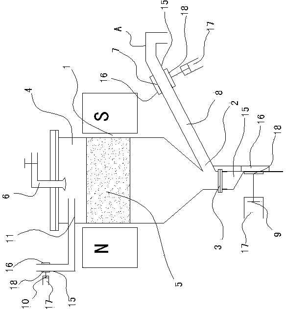
[0014] Embodiment 1: as figure 1 As shown, the fluid iron removal device of the present invention includes a magnetic field 1 formed by the opposite poles of an electromagnetic device or a permanent magnet, a channel 4 made of a non-magnetic material with a finished product outlet 2 and a waste slurry discharge port 3, and a set The soft magnetic medium 5 in the middle and upper part of the channel 4 is provided with a cleaning liquid spraying device 6 and a fluid inlet 11 with a valve 10 at the upper entrance of the channel 4. The special feature is that the finished product outlet 2 with the valve 7 is located at On the side below the channel 4, the finished product outlet 2 is connected with an upwardly inclined conduit 8, the highest point A of the conduit 8 is located below the soft magnetic medium 5, and the waste slurry discharge port 3 with a valve 9 is located at the bottom of the channel 4. The valve 10 on the fluid inlet 11 and the valve 7 on the finished product ou...

Embodiment 2

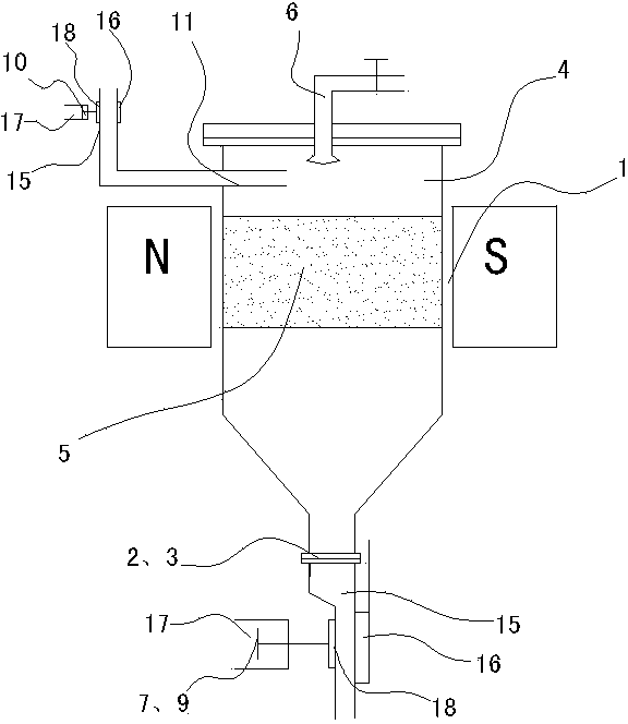
[0016] Embodiment 2: as figure 2 As shown, this embodiment is based on Embodiment 1, the finished product outlet 2 and the waste slurry discharge port 3 are the same outlet, and the valves 7 and 9 on the outlets 2 and 3 include hoses 15 and valves arranged on the hoses 15. The block 16 on one side and the pressing block 18 driven by the cylinder 17 are arranged on the other side of the hose 16. The block 16 moves synchronously with the movement of the channel 4 .

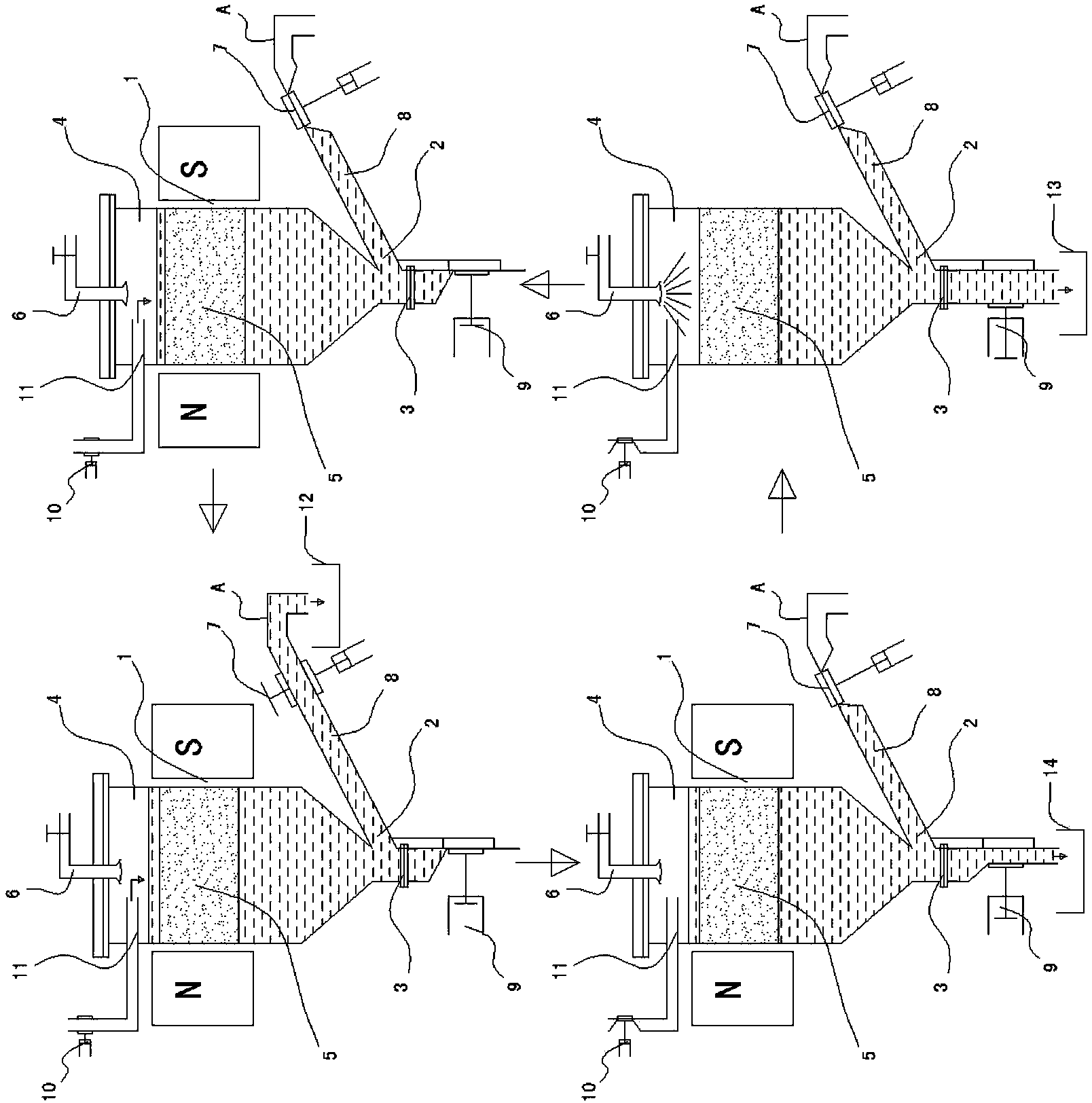
[0017] Such as image 3 As shown, the fluid iron removal method of the present invention is realized in this way, including the fluid iron removal process and the soft magnetic medium cleaning process. The channel 4 of the magnetic medium 5, the fluid after removing the ferromagnetic substance is introduced into the finished product collection container 12, and its special feature is that when the fluid in the process of removing the ferromagnetic substance starts to be introduced into the vertical channel 4 from ...


PUM


Abstract

The invention discloses fluid iron removal method and device. The device comprises a magnetic field, a channel and a soft magnetic medium, wherein the magnetic field is formed by opposite north and south poles of an electromagnetic device or a permanent magnet; the channel is provided with an end product outlet and a waste slurry discharge port and made of a non-magnetic conduction material; the soft magnetic medium is arranged at the inner middle upper part of the channel; and a cleaning solution sprinkler is arranged on the channel. The device is characterized in that the end product outlet with a valve is located at the side of the lower surface of the channel; the end product outlet is connected with an inclined upward conduit; the peak of the conduit is located below the soft magnetic medium; the waste slurry discharge port with a valve is located at the bottom of the channel or the end product outlet and the waste slurry discharge port are a same outlet; the valve at the outlet comprises a hose, a stop dog which is arranged at one side of the hose and a pressing block which is arranged at the other side of the hose and driven by an air cylinder; and the stop dog synchronously moves along with the movement of the channel. Compared with the prior art, the device has favorable effect of removing the iron magnetic substances in the fluids, and has the advantages of having less residual slurry and not removing the iron magnetic substances on the soft magnetic medium during the residual slurry discharging.

Description

Technical field: [0001] The invention relates to a fluid iron removal technology. Background technique: [0002] The existing ceramic slurry iron removal is carried out by introducing the ceramic slurry into the channel filled with soft magnetic medium in a north-south magnetic field. When the soft magnetic medium is full of ferromagnetic substances, it is necessary to carry out Cleaning, to remove the ferromagnetic substances adsorbed on the soft magnetic medium, so as to re-enter the work of removing ferromagnetic substances in the fluid. There are two ways to introduce ceramic slurry into the channel filled with soft magnetic medium, one is to introduce from bottom to top, and the other is to introduce from top to bottom. The way of importing from bottom to top is easy to ensure that the ceramic slurry always overflows the soft magnetic medium in the process of removing ferromagnetic substances, so that there are only two phases of solid and liquid in the fluid, whic...

Claims


Application Information

Patent Timeline
Patent Type & Authority Patents(China)
IPC IPC(8): B03C1/32
Inventor 李泽
Owner 李泽
Learn More