Forming method and device for thin-wall T-pipe
A tee pipe and thin-walled technology, applied in the field of thin-walled tee pipe forming methods and devices, can solve the problems of long cycle time and high cost of tee pipes, and achieve the effects of good mechanical properties, easy processing, and convenient production
- Summary
- Abstract
- Description
- Claims
- Application Information
AI Technical Summary
Problems solved by technology
Method used
Image

Examples
Embodiment 1
[0020] Such as figure 2 shown.
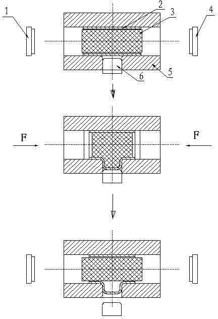
[0021] A kind of thin-walled tee pipe forming method, it comprises the following steps:
[0022] First, put the thin-walled pipe 2 to be formed into the forming mold 5, and put the elastic force transmission medium 3 in the thin-walled pipe 2 (elastic mandrel with high pressure resistance and good mechanical properties can be used, such as a plastic rod), The elastic force transmission medium 3 should be filled with thin-walled pipe fittings 2;
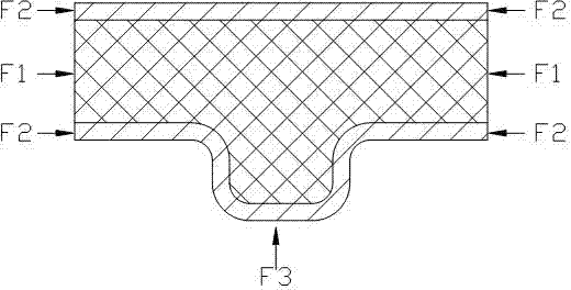
[0023] Secondly, apply pressure F to the elastic force transmission medium 3 from both ends of the thin-walled pipe, so that the elastic force transmission medium 3 fills the lumen and generates a bulging force;
[0024] Third, the elastic force transmission medium is further gradually increased and deformed, and the bulging force is also gradually increased. At the same time, force is applied to both ends of the thin-walled pipe to force the thin-walled pipe to deform in the forming mold to supplem...
Embodiment 2
[0027] Such as image 3 shown.
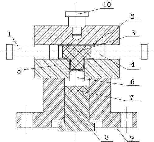
[0028] A thin-walled three-way pipe forming device, which includes a forming die 5, an elastic force transmission medium 3, a left punch 1, a right punch 4, a lower ejector rod 6, a rubber pad 7, a lower mold base 9 and an adjustment nail 8, The forming die 5 is composed of an upper half die and a lower half groove. The upper half die is connected with a connecting block 10 for lifting. The forming die 5 is installed on the lower die base 9. The adjusting nail 8 is located in the lower die base 9. The rubber pad 7 is installed on the adjustment nail 8, the lower part of the lower ejector rod 6 is offset against the rubber pad 7, and the upper end of the lower ejector rod 6 is inserted into the cavity of the forming mold 5 for the extension of the branch pipe to control the plastic deformation of the branch pipe. Forming speed and end surface quality, the cavity is located on the lower half die, the elastic power transmission medium 3 is instal...
PUM
 Abstract
Description
Claims
Application Information
 - Generate Ideas
- Intellectual Property
- Life Sciences
- Materials
- Tech Scout
- Unparalleled Data Quality
- Higher Quality Content
- 60% Fewer Hallucinations
Browse by: Latest US Patents, China's latest patents, Technical Efficacy Thesaurus, Application Domain, Technology Topic, Popular Technical Reports.
© 2025 PatSnap. All rights reserved.Legal|Privacy policy|Modern Slavery Act Transparency Statement|Sitemap|About US| Contact US: help@patsnap.com