Shaped deburring cutter

A technology of burr cutter and cutter body, which is applied in the attachments of tool holders, tools for lathes, turning equipment, etc., can solve the problems of narrow application range and single function, and achieve the effect of simple and applicable structure.

Active Publication Date: 2013-03-13
南通星汉机械有限公司
View PDF8 Cites 4 Cited by
  • Summary
  • Abstract
  • Description
  • Claims
  • Application Information

AI Technical Summary

Problems solved by technology

The utility model solves the problems of single function and narrow application range in the existing circular blades

Method used


Image

  • Shaped deburring cutter
  • Shaped deburring cutter
  • Shaped deburring cutter

Examples


Embodiment Construction

[0015] Further illustrate by the following examples.

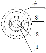
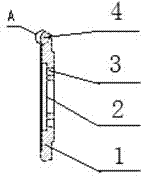
[0016] There is a shaft hole 2 in the middle of the cutter body 1, and a knife edge 4 is formed on one side of the disc-shaped cutter body 1, and arc teeth 5 are evenly distributed on the knife edge 4.

[0017] Slotted holes 3 are evenly distributed around the shaft hole 2 in the middle of the cutter body 1 .

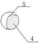
[0018] The arc teeth 5 are evenly distributed on the blade edge 4, wherein the radial ridges of the arc teeth 5 on the surface edge of the cutter body 1 are arc-shaped, and the arc teeth 5 are concave between adjacent ridges and are inclined to one side of the ridge.

[0019] In the foregoing, the upper arc teeth 5 of the knife edge 4 are composed of two opposite half circles, and their concave inclination directions are opposite. In the latter, two kinds of arc teeth 5 with opposite concave inclination directions are distributed at intervals.

[0020] When the present invention is working, it is fixed on the equip...


PUM


Abstract

The invention relates to a shaped deburring cutter. The middle of a cutter body (1) is provided with a shaft hole (2), the circumference of one side of the disk-shaped cutter body (1) is provided with a cutter edge (4), and curved teeth (5) are uniformly distributed on the cutter edge (4). Since the curved teeth are uniformly distributed on the cutter edge, the structure is simple and applicable, and the shaped deburring cutter can be used for scraping , trimming and deburring tools and castings made of various materials, and can be widely applied in machining and mould production. The shaped deburring cutter not only can be conveniently rotated clockwise and counterclockwise to remove burrs, but also can process complex machined surfaces.

Description

technical field [0001] The invention relates to tools for international patent classification B23B turning, boring or B24D grinding, polishing or sharpening, belonging to the technical field of deburring gear end faces, in particular to forming deburring knives. Background technique [0002] In the prior art, gears processed by gear hobbing machines and gear shaping machines have many burrs on the cutting surface. In some places, it is difficult to deburr with a file, and it takes a long time to deburr with a file. The application of a special deburring knife The corresponding situation has been improved. However, the existing deburring knives mostly use a working surface with protruding edges. For example, they are relatively restricted in the deburring process. The existing deburring knife clamps the gear to complete the deburring process. , can only process the side of ordinary gears. [0003] In the known technologies, especially the chamfering tools and technologies ...

Claims


Application Information

Patent Timeline
Patent Type & Authority Applications(China)
IPC IPC(8): B23F21/00B23B27/00
Inventor 蒋能
Owner 南通星汉机械有限公司
Why Eureka
Try Eureka