Centrifugal rotary cutting mechanism for thermal shrinkage pipe

A heat-shrinkable tube and cutting technology, which is applied in metal processing and other directions, can solve the problems of oblique cutting and uneven cutting, and achieve the effect of improving cutting production efficiency.

Active Publication Date: 2015-01-28
CHANGYUAN ELECTRONICS DONGGUAN +3
View PDF6 Cites 0 Cited by
  • Summary
  • Abstract
  • Description
  • Claims
  • Application Information

AI Technical Summary

Problems solved by technology

[0003] The technical problem to be solved by the present invention is: to overcome the problem that cutting the heat-shrinkable tube in the prior art is easy to cause the cutting bevel and the cutting edge is not smooth, and propose a centrifugal rotary cutting method that can effectively avoid the above defects and greatly improve the cutting production efficiency. mechanism

Method used


Image

  • Centrifugal rotary cutting mechanism for thermal shrinkage pipe
  • Centrifugal rotary cutting mechanism for thermal shrinkage pipe
  • Centrifugal rotary cutting mechanism for thermal shrinkage pipe

Examples


Embodiment Construction

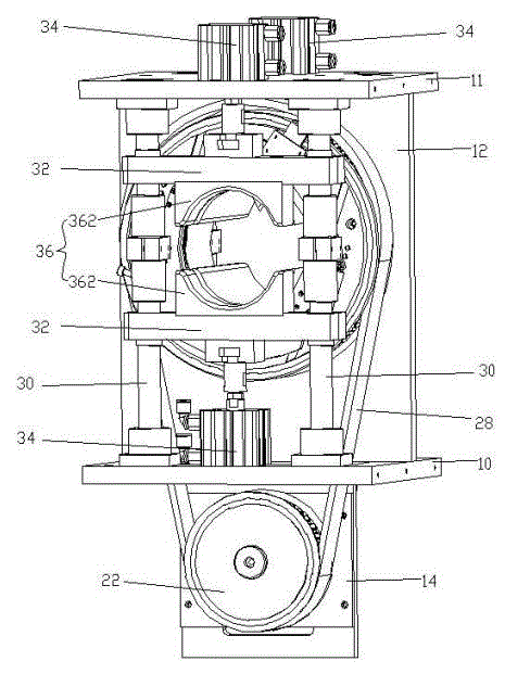
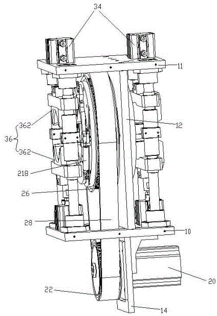
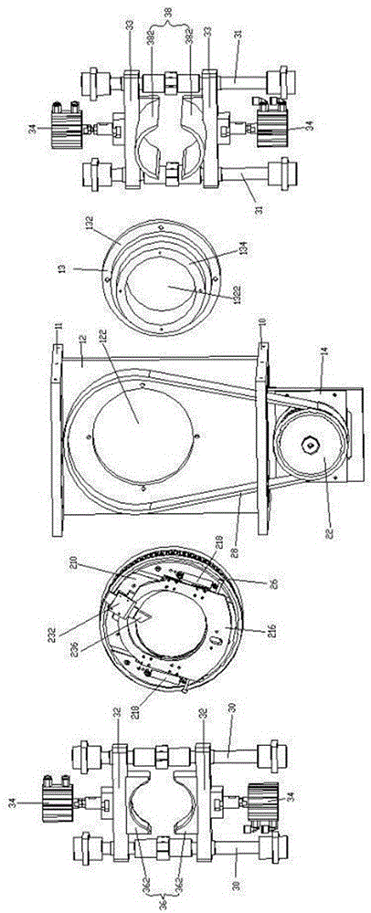
[0031] see Figure 1 to Figure 11 , a centrifugal rotary cutting machine for heat-shrinkable tubes, which includes a frame (not labeled), a clamp mechanism (not labeled), and a centrifugal rotary cutting mechanism (not labeled).

[0032] The frame (not labeled) includes a support plate 12 , a support seat 13 , and a motor mounting plate 14 .

[0033] The support plate 12 is installed vertically. A circular through hole 122 is defined on the support plate 12 .

[0034] The support seat 13 includes a circular seat body 132, a circular through hole 1322 is opened in the center of the seat body 132, and a circular bearing mounting seat protrudes along the edge of the through hole 1322 on the seat body 132. 134. The supporting seat 13 is fixed on the supporting plate 12 , and the bearing mounting seat 134 passes through the through hole 122 .

[0035] This fixture mechanism (unlabeled) comprises a bottom plate 10, a top plate 11, two front guide pillars 30, two rear guide pilla...


PUM


Abstract

The invention discloses a centrifugal rotary cutting mechanism for thermal shrinkage pipes. A first synchronizing belt wheel is mounted on a rotating shaft of a servo motor, second synchronizing belt wheels are mounted on a plurality of bearings, and a synchronizing belt is mounted to the first and the second synchronizing belt wheels. Cutting die holders are fixedly arranged on the second synchronizing belt wheels, and a through-hole is formed in the center of each cutting die holder. Two sliding tracks are fixedly arranged on two sides of the through-holes on the cutting die holders. A plurality of sliders are arranged on the two sliding tracks in a sliding manner. An elliptic through-hole is formed in the center of a centrifugal follow-up block. Two springs are arranged on two sides of the centrifugal follow-up block respectively, the lower ends of the springs are arranged at the lower end of the centrifugal follow-up block, and the upper ends of the springs are arranged on the cutting die holders. A cutting knife is fixedly arranged at the top of the follow-up block and positioned at the upper end of the through-holes. The centrifugal rotary cutting mechanism provided by the invention performs the cutting operation in the centrifugal mode, effectively avoids the defects of squeezed flat cut end, oblique cut end and uneven cut end, and can greatly increase the cutting efficiency.

Description

technical field [0001] The invention relates to a cutting mechanism for heat-shrinkable tubes. The cutting mechanism can effectively avoid defects such as flattening of the cutting edge, beveled cutting edge, and uneven cutting edge through centrifugal cutting, and greatly improve the cutting production. efficiency. Background technique [0002] At present, in the heat-shrinkable industry, the diameter of the heat-shrinkable tube varies widely (φ0.8--φ180mm), and the tube wall is thin (0.26-1.55mm). There are many problems in the cutting of the heat-shrinkable tube, such as: the cutting edge is pressed Flat, oblique cutting, uneven cutting, low cutting production efficiency. Contents of the invention [0003] The technical problem to be solved by the present invention is: to overcome the problem that cutting the heat-shrinkable tube in the prior art is easy to cause the cutting bevel and the cutting edge is not smooth, and propose a centrifugal rotary cutting method that ...

Claims


Application Information

Patent Timeline
Patent Type & Authority Patents(China)
IPC IPC(8): B26D1/25B26D5/08B26D7/26B26D7/02
Inventor 柏禹卢真光刘晓播
Owner CHANGYUAN ELECTRONICS DONGGUAN
Why Eureka
Try Eureka