A flexible and configurable guide wire and a manufacturing method thereof

A flexible and guide wire technology, applied in the field of medical devices, can solve the problems of high production cost, complex production process, poor solder biocompatibility, etc., and achieve the effect of reduced manufacturing cost, simple processing technology and better compatibility

Pending Publication Date: 2019-01-04
巴特勒生物科技(苏州)有限公司
View PDF9 Cites 4 Cited by
  • Summary
  • Abstract
  • Description
  • Claims
  • Application Information

AI Technical Summary

Problems solved by technology

[0004] This widely used method of processing the guide wire has the following disadvantages: First, because the core wire needs to be inserted into the spring coil and fixed by brazing in the production process, the production process is relatively complicated and the production cost is high; secondly, due to the brazing , between the two parts is prone to unevenness, resulting in poor compatibility with the device during use; the final brazing solder is generally poor in biocompatibility, and the current conventional production can only be reduced by controlling the amount harm to the human body

Method used


Image

  • A flexible and configurable guide wire and a manufacturing method thereof
  • A flexible and configurable guide wire and a manufacturing method thereof
  • A flexible and configurable guide wire and a manufacturing method thereof

Examples


Embodiment 1

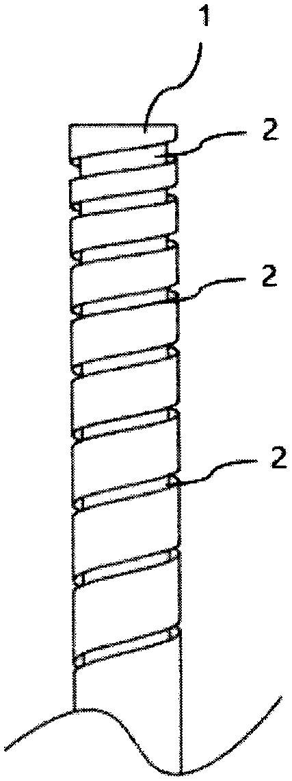
[0038] Such as figure 1 As shown, a plurality of groove units 2 are arranged in a spiral structure, and the shape of the groove units 2 is straight. The plurality of groove units 2 are connected end to end, and finally the plurality of groove units 2 form a helix on the outer surface of the metal wire 1 . In order to make the flexibility of the guide wire meet the required requirements, the pitch of the helix can be adjusted, and the smaller the pitch, the better the flexibility.

Embodiment 2

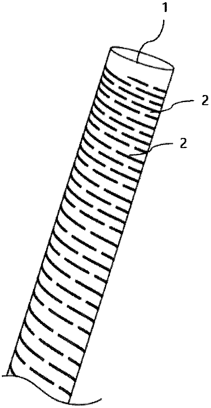
[0040] Such as figure 2 As shown, a plurality of the groove units 2 are arranged in a double-start thread-like structure, the shape of the groove units 2 is linear, and a plurality of the groove units 2 are arranged at intervals from each other, and the groove units The groove depth of 2 is greater than the radius of the metal wire 1 and smaller than the diameter of the metal wire 1 . The double-threaded structure is mirror-symmetrically arranged with respect to the axial section of the metal wire 1. When there are groove units at the same axial position of the metal wire 1 at a distance of 180 degrees, the opposite groove unit is The slits are interconnected to form slits; in this way, there are three states in the axial direction of the metal wire 1: uncut, a single groove unit, and slits formed by opposite groove units. By changing the proportions of these three states on the wire 1, the flexibility of the guide wire can be set.

Embodiment 3

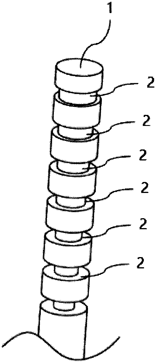
[0042] Such as image 3 As shown, a plurality of the groove units 2 are arranged into a plurality of ring structures, the shape of the groove units 2 is straight, and the plurality of groove units in the same ring structure are connected end to end , and finally form a plurality of annular grooves on the outer peripheral surface of the wire. The surfaces formed by the ring structures are planes parallel to each other, and the distances between them are equal. The groove width of the groove unit is fixed and smaller than the diameter of the metal wire 1 . The groove depths of the groove unit 2 are different and smaller than the radius of the wire. The deeper the groove depth is, the better the flexibility of the metal wire is, and the flexibility of the guide wire can be set by adjusting the depth of the groove unit 2 .


PUM


Abstract

The invention relates to a flexible and configurable guide wire and a manufacturing method thereof. The flexible and configurable guide wire is made of a single metal wire, and a groove is arranged onthe metal wire, and the groove is formed by a plurality of groove units in an arrangement and combination manner. The invention is only made of a single metal wire, avoids fixing between traditionalguide wire parts, and has low defective rate of the product. And the processing technology is simple and the product cost is low.

Description

technical field [0001] The invention relates to the field of medical devices, in particular to a guide wire with adjustable flexibility and a manufacturing method thereof, which are used to assist in introducing catheters or other devices into lumens in the body, so as to facilitate diagnosis or treatment of diseases. Background technique [0002] Guide wires have been widely used to assist in the introduction of catheters or other instruments into lumens in the body for diagnosis or treatment of diseases. For example, in vascular surgery, the guide wire is usually used to assist the percutaneous introduction of the catheter into the blood vessel or push the stent to the affected part of the blood vessel. In the diagnosis and treatment of gastrointestinal tract, the guide wire is inserted into the guide wire lumen of the endoscope to guide the surgical instruments matched with the endoscope to the target position. [0003] The existing guide wire commonly used in the market...

Claims


Application Information

Patent Timeline
Patent Type & Authority Applications(China)
IPC IPC(8): A61M25/09
CPCA61M25/09A61M2025/09108A61M2025/09133
Inventor 刘恒全刘爱华邓双
Owner 巴特勒生物科技(苏州)有限公司
Why Eureka
Try Eureka