
Magnetic suspension vehicle travelling unit in traction linear motor

A linear motor and magnetic levitation technology, applied in electric traction, electric vehicles, vehicle parts, etc., can solve the problems of reducing natural air cooling heat dissipation efficiency, reducing motor efficiency, increasing motor current, etc. The effect of improving heat dissipation efficiency and increasing the size of the motor

Inactive Publication Date: 2013-03-13
NAT UNIV OF DEFENSE TECH
View PDF4 Cites 22 Cited by
  • Summary
  • Abstract
  • Description
  • Claims
  • Application Information

AI Technical Summary

Problems solved by technology

The shading of the supporting arms at both ends reduces the heat dissipation efficiency of natural air cooling, thus limiting the improvement of traction power by increasing the motor current
[0008] 2. In the prior art, the traction linear motor is arranged on the suspension module, and moves with the left and right suspension modules respectively when driving, and factors such as suspension control fluctuations, roll of the suspension module when landing, track irregularities, and seam staggering are considered. , the fluctuation range of the motor air gap is large, so the design value of the motor air gap is large, which reduces the efficiency of the motor

Method used


Image

  • Magnetic suspension vehicle travelling unit in traction linear motor
  • Magnetic suspension vehicle travelling unit in traction linear motor
  • Magnetic suspension vehicle travelling unit in traction linear motor

Examples


Embodiment Construction

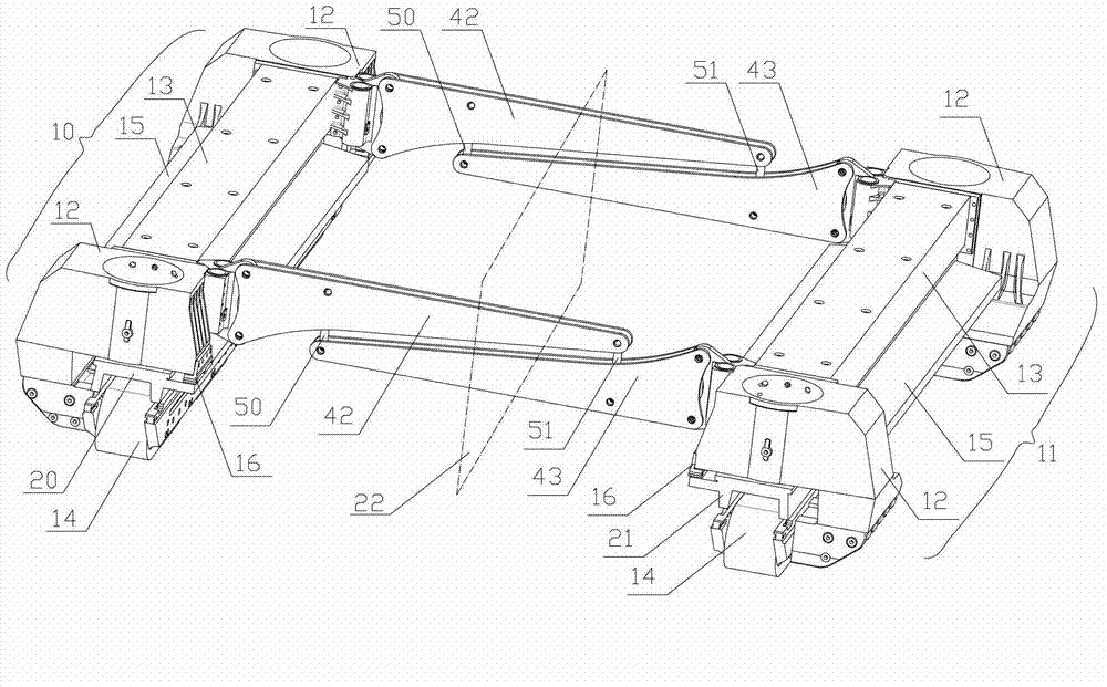
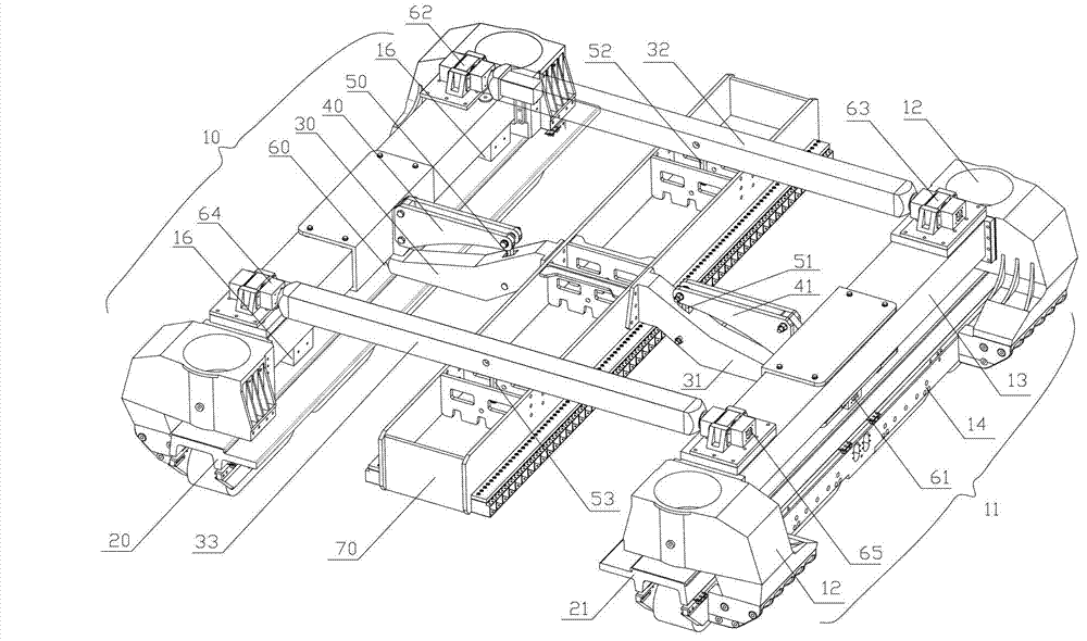
[0032] image 3 It is a three-dimensional structural diagram of the walking unit of the present invention; as image 3 As shown, the present invention is composed of two independent suspension modules, a traction linear motor 70, two beams, four sets of beam ball hinge linear combined bearings, two motor suspension rods and a set of anti-roll mechanism. Similar to the existing running unit, the left suspension module 10 of the present invention is arranged on the left side of the track, and the right suspension module 11 is arranged on the right side of the track. Different from the existing running unit, the traction linear motor 70 is arranged between the left suspension module 10 and the right suspension module 11 to reduce the limiting factor of the motor size. Traction linear motor 70 is placed on the middle part of running unit, is hoisted on the middle part of front end crossbeam 32 by front motor suspender 52, is hoisted on the middle part of rear end crossbeam 33 by ...


PUM

PropertyMeasurementUnit
Dampingaaaaaaaaaa

Abstract

The invention discloses a magnetic suspension vehicle traveling unit in a traction linear motor. The purpose is to solve the problems of arrangement and installation of a large traction linear motor in the magnetic suspension vehicle travelling unit. The magnetic suspension vehicle travelling unit consists of two suspension modules, a traction linear motor, two cross beams, four sets of cross beam spherical hinge linear combination bearings, two motor hanging rods and a set of rolling prevention mechanism, wherein the traction linear motor is arranged in a middle surface position between the two suspension modules and is suspended in the middle of the front and back cross beams through the front and back motor hanging rods, and the rolling prevention mechanism consists of two main arms, two rolling prevention beams, two rolling prevention hanging rods and two sets of main arm spherical hinge linear combination bearings and is distributed on a middle cross section of the travelling unit. According to the magnetic suspension vehicle travelling unit, the limit on the size of the motor is remarkably reduced, the traction power is promoted to be increased through increasing the size of the motor or the current, the acceleration and the deceleration of a vehicle are improved, an air gap and the fluctuation of the air gap of the motor are reduced, and the efficiency is improved.

Description

technical field [0001] The invention relates to a running unit of a magnetic levitation vehicle, in particular to a running unit of a magnetic levitation vehicle in which a traction linear motor is arranged horizontally between left and right levitation electromagnets. Background technique [0002] Maglev transportation technology originated in the 1930s, developed significantly at the end of the 20th century, and gradually moved towards commercial operation. Maglev vehicles have the advantages of fast speed, small turning radius, strong climbing ability, and low noise pollution, and are especially suitable as a modern means of transportation between cities and between cities. [0003] "Journal of Sun Yat-Sen University (Natural Science Edition)" Volume 47 Supplement 2 paper "Research on Coupling Dynamics Simulation of Low-speed Urban Rail Maglev Vehicle" published a three-dimensional structure diagram of the running unit of a medium-low speed maglev vehicle, as shown in fi...

Claims


Application Information

Patent Timeline
IPC IPC(8): B60L13/10
Inventor 刘耀宗邓文熙黎利华龚朴李云钢刘恒坤程虎董钟
Owner NAT UNIV OF DEFENSE TECH
Learn More