Paper sludge transfer and storage silo

A papermaking sludge and storage silo technology, applied in the directions of transportation and packaging, loading/unloading, containers, etc., can solve the problems of material blockage at the outlet of the sludge storage hopper, increased labor costs, high viscosity, etc., and achieves high service life. Avoid bridging and high blanking efficiency

Active Publication Date: 2013-03-13
MCC NORTH (DALIAN) ENG TECH CO LTD
View PDF9 Cites 7 Cited by
  • Summary
  • Abstract
  • Description
  • Claims
  • Application Information

AI Technical Summary

Problems solved by technology

At present, the storage hoppers designed in the industry are conical storage hoppers with a large top and a small bottom. Since the bottom outlet is usually a square hole of about 300X300, the storage hopper wall cannot be made into a vertical type. It must have a certain slope, and then it is affected by the height of the factory building. Due to the limitation of the volume of the storage hopper, the slope of the storage hopper is generally 65o~75o. Due to the high water content and high viscosity of the papermaking sludge, the sludge storage hopper in front of the furnace often encounters the problem of sludge bridging
Even if the commonly used coal-screwing machine is used, the effect is not obvious. The reason is that the coal-screwing machine cannot solve the problem of bridging all parts of the silo from top to bottom. The bottom outlet of the sludge storage hopper is often blocked, and the material cannot rely on gravity at the bottom. The natural fall, the operator often uses the method of beating the warehouse wall or stabbing the material downward with a steel pipe from the cabin roof to temporarily solve the problem. If there is a serious bridging situation, it will affect the feeding in front of the furnace, which greatly increases the labor cost and troubles the operation. personnel

Method used


Image

  • Paper sludge transfer and storage silo
  • Paper sludge transfer and storage silo
  • Paper sludge transfer and storage silo

Examples


Embodiment Construction

[0025] The specific implementation manner of the present invention will be described below in conjunction with the accompanying drawings.

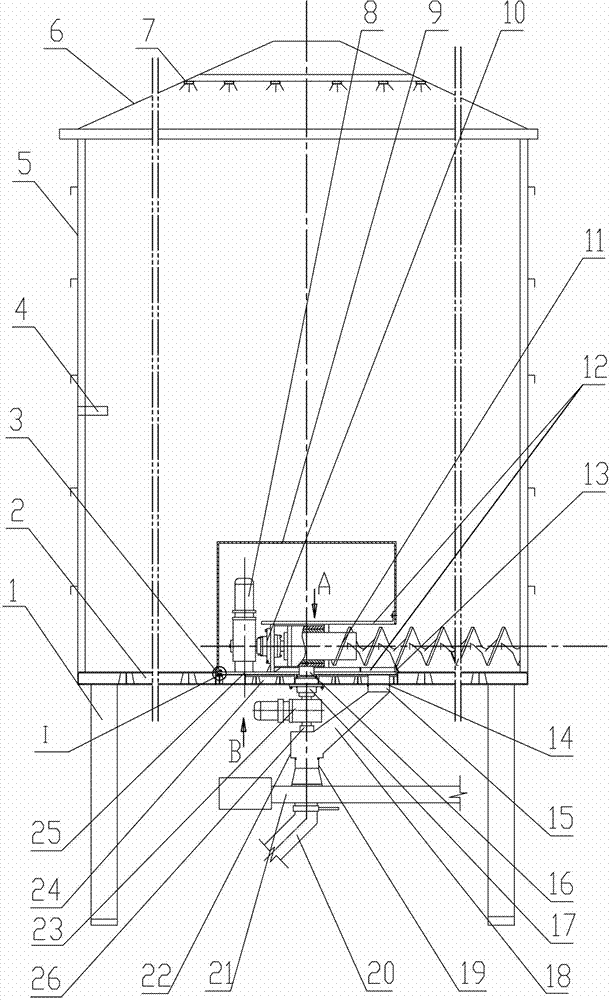
[0026] Such as figure 1 As shown, the papermaking sludge transfer storage bin of the present invention is characterized in that: it includes a closed bin body with a cylindrical inner cavity, a screw feeder and a bottom axial flow fan arranged on the bottom of the closed bin body, A group of fire extinguishing nozzles 7 arranged on the top of the closed warehouse body, a material level gauge 4 arranged in the middle of the closed warehouse body, a double-end output driving device 23 arranged on the bottom of the closed warehouse body, and the double-ended The discharge chute connected to the output lower end of the output driving device 23, the belt feeding hopper 19 that is slidingly connected with the bottom of the discharge chute, the belt conveyor 21 that is located below the belt feeding hopper 19 and the belt conveyor that is located...


PUM


Abstract

The invention belongs to the technical field of a paper sludge incineration device, and particularly relates to a paper sludge transfer and storage silo, which comprises a sealed silo body, a screw feeder, a bottom axial-flow fan, a group of fire fighting nozzles, a material level meter, a double-end output drive device, a discharging chute, a belt feeding hopper, a belt conveyor and an accident ash-discharging pipe. The sealed silo body consists of a steel structural framework, a combined disc type bottom plate, a cylindrical silo wall and an umbrella-shaped silo roof, wherein the combined disc type bottom plate consists of a fixed disc, a rotary disc, a vertical rotating shaft and a base bracket, the fixed disc consists of a ring-shaped fixed plate, a central fixed plate and a ring-shaped power supply sliding contact line, and the rotary disc is provided with a sludge outlet, a ventilating manhole and a mounting hole. The sealed silo body is suitable for rotation and mixing of materials in the silo and the service life of the silo body is long. The screw feeder has the functions of revolution and rotation. Materials can be delivered into an appropriate position due to rotation while being mixed under effects of revolution, the problem of bypass of sludge materials can be avoided, and the efficiency of transfer and falling is high.

Description

technical field [0001] The patent of the invention belongs to the technical field of papermaking sludge incineration equipment, and in particular relates to a papermaking sludge transfer storage bin. Background technique [0002] In the feeding process of papermaking sludge incineration, it is necessary to use the sludge storage hopper in front of the furnace to store the sludge to buffer and store the material and achieve the purpose of uniform feeding in front of the furnace through the front feeder arranged at the bottom of the furnace. At present, the storage hoppers designed in the industry are conical storage hoppers with a large top and a small bottom. Since the bottom outlet is usually a square hole of about 300X300, the storage hopper wall cannot be made into a vertical type. It must have a certain slope, and then it is affected by the height of the factory building. Due to the limitation of the volume of the storage hopper, the slope of the storage hopper is ge...

Claims


Application Information

Patent Timeline
Patent Type & Authority Applications(China)
IPC IPC(8): B65D88/68B65D90/22B65G65/46B65G65/42
Inventor 杨肇博宋冀鹏
Owner MCC NORTH (DALIAN) ENG TECH CO LTD
Why Eureka
Try Eureka