Plunger type supply device

A supply device, plunger-type technology, applied in the direction of transportation and packaging, conveyor objects, etc., can solve the problems of poor separation effect, low feeding speed, time-consuming and labor-intensive, etc., to achieve simple structure, fast supply speed, easy to use convenient effect

Inactive Publication Date: 2013-03-13
CHONGQING TIANZHIDAO SCI & TECH DEV
View PDF0 Cites 6 Cited by
  • Summary
  • Abstract
  • Description
  • Claims
  • Application Information

AI Technical Summary

Problems solved by technology

[0002] The workpiece supplied from the workpiece feeder is usually transported to the processing machine or assembly machine by using a gravity chute. The disadvantages are: first, some workpieces will be blocked in the middle of the chute, which requires manual troubleshooting, which is time-consuming and laborious. The material speed is low; secondly, when the existing feeder separates the bottom-shaped workpiece from the cylinder, the separation effect is not good and the speed is slow

Method used


Image

  • Plunger type supply device

Examples


Embodiment Construction

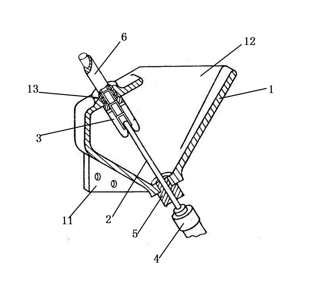
[0010] refer to figure 1 , a plunger type supply device, including a feeding mechanism, a separation mechanism and an output mechanism, the feeding mechanism includes a funnel 1, the funnel 1 is installed on the frame through a connecting plate 11, and the head of the funnel 1 has a feeding opening 12 And the discharge hole 13, the neck of the funnel 1 is a hollow columnar structure.

[0011] The separation mechanism includes a plunger 2, a clamp finger 3 and a cylinder 4 that controls the expansion and contraction of the plunger. The free end of the plunger 2 extends from the neck of the funnel 1, and the seal between the plunger 2 and the neck of the funnel 1 is sealed by a sealing plug 5. The clamp finger 3 is fixed on the inner side of the discharge hole 13, and the clamp finger 3 can accommodate workpieces arranged in a single row. Driven by the cylinder 4, the plunger 2 expands and contracts axially along the clamp finger 3, and pushes the workpiece in the head of the f...


PUM


Abstract

The invention discloses a plunger type supply device which comprises a feeding mechanism, a separating mechanism and an output mechanism; the feeding mechanism comprises a funnel; a feeding opening and a discharging hole are formed on the funnel; a connecting plate is arranged on the outer wall of the funnel; the separating mechanism comprises a plunger, a clamping finger and an air cylinder for controlling the plunger to expand or contract; the clamping finger is arranged on the inner side of the discharging hole of the funnel; the free end of the plunger extends in from the neck part of the funnel and can expand or contract axially along the clamping finger; and the output mechanism comprises a transportation pipe arranged on the outer side of the discharging hole of the funnel. The plunger type supply device provided by the invention has the advantages of simple structure, high supply speed, low blockage rate, stability in running, and convenience in use.

Description

technical field [0001] The invention relates to a plunger type supply device, which belongs to the field of supply devices. Background technique [0002] The workpiece supplied from the workpiece feeder is usually transported to the processing machine or assembly machine by using the gravity chute. The disadvantages are: first, some workpieces will be blocked in the middle of the chute, which requires manual troubleshooting, which is time-consuming and laborious. The material speed is low; secondly, when the existing feeder separates the bottom-shaped workpiece of the cylinder, the separation effect is not good and the speed is relatively slow. Contents of the invention [0003] The present invention intends to provide a plunger-type feeding device with low clogging rate and suitable for separating cylindrical bottom-shaped workpieces. [0004] The object of the present invention can be achieved by the following measures: a plunger type supply device, comprising a feed me...

Claims


Application Information

Patent Timeline
Patent Type & Authority Applications(China)
IPC IPC(8): B65G47/74B65G47/82
Inventor 姜静慧
Owner CHONGQING TIANZHIDAO SCI & TECH DEV
Why Eureka
Try Eureka