

Hydraulic clasp brake control device
A control device and hydraulic technology, which is applied in the field of hydraulic brake control devices and hydraulic brake devices, can solve problems such as malfunction, waste of energy, failure of mechanical brakes, etc., and achieve the effect of ensuring effectiveness and reliability
Inactive Publication Date: 2013-03-13
何淑强
View PDF0 Cites 0 Cited by
- Summary
- Abstract
- Description
- Claims
- Application Information
AI Technical Summary
Problems solved by technology
[0003] The purpose of the present invention is to provide a hydraulic brake control device, which overcomes the fact that the oil pump of the hydraulic system in the existing hydraulic device needs to work continuously, which not only wastes a certain amount of energy, but also easily leads to failure of the mechanical brake and cannot work normally. Defects
Method used
View moreImage
Smart ImageViewing Examples

Examples
Embodiment Construction
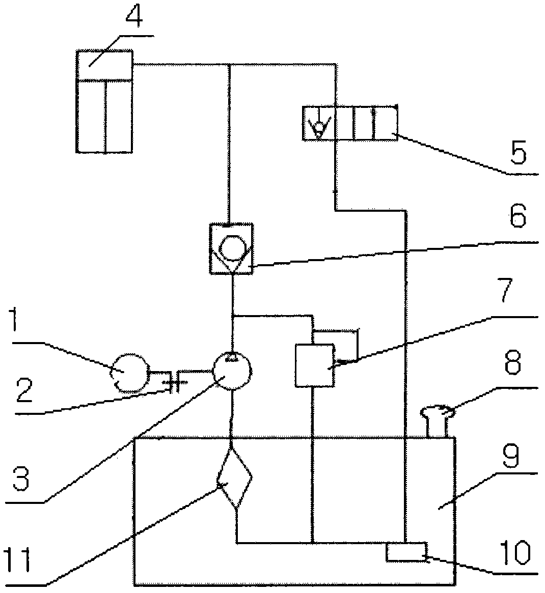
[0009] The hydraulic brake control device has a relief valve (7), and an air-steam filter (8) is connected along the relief valve (7). The lower end of the air-steam filter (8) is connected to a fuel tank (9). The inner lower end of (9) is connected with an intermediate relay (10), and the intermediate relay (10) is connected with the filter (11), and a hydraulic pump (3) is connected at the upper end of the filter (11), and the hydraulic pump (3) The upper end is connected with a check valve (6), and the two ends of the check valve (6) are connected with the solenoid valve (2) and the single-acting oil cylinder (4).
Login to View More PUM
 Abstract
The invention discloses a hydraulic clasp brake control device. The hydraulic clasp brake control device comprises a pressure meter, a coupling, a hydraulic pump, a single-acting oil cylinder, an electromagnetic valve, a one-way valve, an overflow valve, an air filter, an oil tank, an intermediate relay and a filter. The hydraulic clasp brake control device is characterized in that the overflow valve is arranged and connected with the air filter, the oil tank is connected with the lower end of the air filter, the intermediate relay is connected with the inner lower end of the oil tank, the intermediate relay is connected with the filter, the upper end of the filter is connected with the hydraulic pump, the upper end of the hydraulic pump is connected with the one-way valve, and the two ends of the one-way valve are connected with the electromagnetic valve and the single-acting oil cylinder. The device is used for monitoring the braking state by adopting a displacement sensor, thereby ensuring the effectiveness and the reliability of braking.
Description
technical field [0001] The invention relates to a hydraulic brake device, in particular to a hydraulic brake control device, which belongs to the technical field of electromechanical equipment. Background technique [0002] At present, on large-scale transportation and lifting equipment such as the construction industry, hydraulic block brakes are generally used to decelerate the equipment and stabilize the vehicle after parking. Because the equipment is in long-term operating conditions, the oil pump of the hydraulic system needs to work continuously, which not only wastes a certain amount of energy, but also easily leads to failure of the mechanical brake and cannot work normally. Contents of the invention [0003] The purpose of the present invention is to provide a hydraulic brake control device, which overcomes the fact that the oil pump of the hydraulic system in the existing hydraulic device needs to work continuously, which not only wastes a certain amount of energ...
Claims
Login to View More Application Information
Patent Timeline
 IPC IPC(8): B66D5/26
Inventor何淑强
Owner何淑强