Expansion pole

A telescopic rod and rod body technology is applied in the field of column-type clothes dryers, which can solve the problems of high production cost, complicated process, easy loosening and the like, and achieve the effects of convenient processing, reliable connection and guaranteed strength.

Inactive Publication Date: 2013-03-13
胡杰波
View PDF5 Cites 13 Cited by
  • Summary
  • Abstract
  • Description
  • Claims
  • Application Information

AI Technical Summary

Problems solved by technology

With this kind of structure, after the telescopic structure of the support rod is used for a long time, the two rods are easy to loosen, and when heavy objects are hung, the two rods are easy to slide, so the two rods cannot be fixed well.
[0005] In addition, in order to prevent the axial relative rotational displacement between the two rods, guide grooves are often provided, which requires the metal pipe rods with guide grooves to be made by hot extrusion and drawing, which is complicated in process and high in production cost.

Method used


Image

  • Expansion pole
  • Expansion pole
  • Expansion pole

Examples


no. 1 example

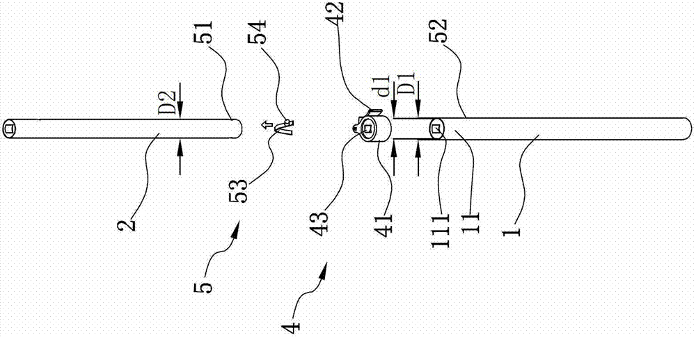
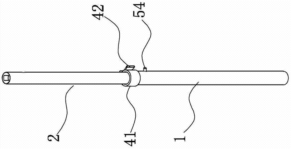
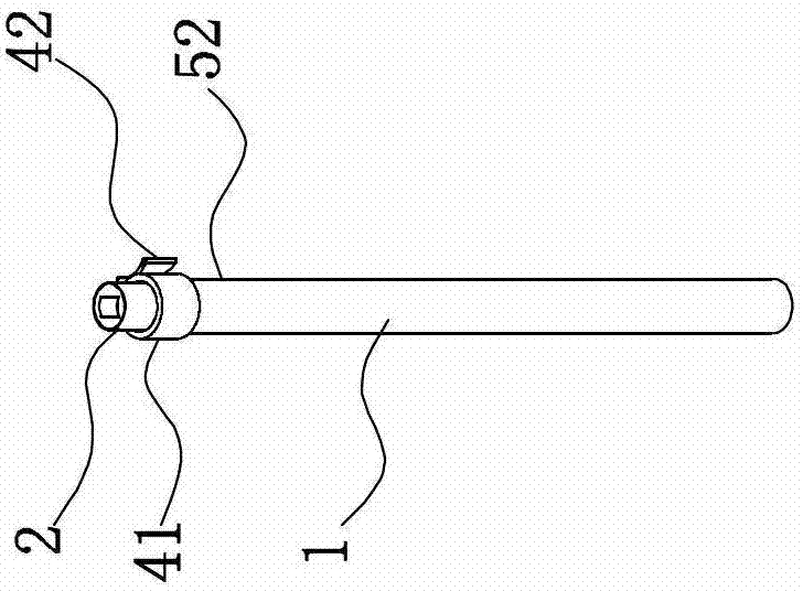
[0038] Such as Figure 1A , 1B , 1C, the first rod body 1 is preferably a round tube made of metal material, its outer diameter is D1 and the inner diameter is d1, the outer diameter of the second rod body 2 is D2, and the outer diameter D2 of the second rod body is smaller than the first rod body. An inner diameter d1 of the rod body 1 . The lower end of the second rod body 2 extends into the first rod body 1, and the second rod body 2 can extend upwards and retract downwards into the first rod body. That is to say, the second rod body 2 can perform a relative linear displacement relative to the first rod body 1 so as to be elongated to obtain a longer rod body.

[0039] A locking device 4, comprising: a sleeve 41, a pull lever 42 and a lock block 43, the pull lever 42 is arranged along the peripheral surface of the sleeve 41, and one end of the pull lever 42 is hinged on the peripheral surface of the sleeve 41, The connection between the trigger lever 42 and the sleeve 41 ...

no. 2 example

[0043] Such as figure 2 As shown, the first rod body 1 is preferably a round tube made of metal material, its outer diameter is D1 and its inner diameter is d1, the outer diameter of the second rod body 2 is D2, and the outer diameter D2 of the second rod body is smaller than that of the first rod body 1 inner diameter d1. The lower end of the second rod body 2 extends into the first rod body 1, and the second rod body 2 can extend upwards and retract downwards into the first rod body. That is to say, the second rod body 2 can perform a relative linear displacement relative to the first rod body 1 so as to be elongated to obtain a longer rod body.

[0044] The telescopic rod has a locking device 4, which includes a socket 41', a tightening hoop 411 located on the upper part of the socket 41', and a tightening nut 42' set outside the tightening hoop 411. The receiving sleeve 41' of the locking device 4 is fixed on the end 11 of the first rod body 1 protruding from the second...

no. 3 example

[0048] Such as Figure 3A , 3B As shown, the difference from the first embodiment is that the sides of the first rod body 1 and the second rod body 2 are respectively provided with shafts along the axis of the first rod body 1 and the second rod body 2 for guiding when the two are mutually telescopic. Extending guide grooves 12, 21. After the mutual expansion and contraction between the first rod body 1 and the second rod body 2 is completed, the direction of the peripheral surface is always kept so as not to rotate with each other.

[0049] Such as Figure 3C As shown, the difference from the second embodiment is that the side surfaces of the first rod body 1 and the second rod body 2 are respectively provided with guide rails along the first rod body 1 and the second rod body 2 for mutual expansion and contraction between the two. Axially extending guide grooves 12, 21.


PUM


Abstract

The invention discloses an expansion pole, which comprises a first pole body; , a second pole body flexible stretched in the first pole body; , a limiting device with a clamp spring and a clamp block located on the clam spring for limiting the second pole body and the first pole body axially and circumferentially; , and a locking device for avoiding preventing the second pole body from shaking in the first pole body radially. The expansion pole in disclosed by the invention is provided with the limiting device for limiting circumferential rotation and axial movement between the two role bodies; , and is provided with the locking device for preventing radial shake and circumferential rotation between the two role bodies; , not only has a simple structure, and is convenient to process, but also has is reliable in connection; and the intensity of the expansion pole can be ensured.

Description

technical field [0001] The invention relates to a column dryer, in particular to a telescopic pole of the dryer. Background technique [0002] The existing column-type clothes dryers and column-type garment steamers in the home appliance market usually have a lower part of a chassis placed on the ground, and a telescopic support rod made of metal material is inserted vertically upward on the chassis. A clothes hanger is installed on the top for hanging clothes, and the weight of the clothes is passed down to the chassis by the support rod. The support rod can adopt a telescopic structure, which is beneficial to reduce the packaging cost of the product and facilitate the transportation and storage of the product. The telescopic support rod is usually composed of multi-segment rods, and the connection structure between the multi-segment rods is usually There are two types: [0003] One is that the first rod body is sleeved with a connecting sleeve at the extension port of th...

Claims


Application Information

Patent Timeline
Patent Type & Authority Applications(China)
IPC IPC(8): F16B7/10D06F58/20
Inventor 胡杰波
Owner 胡杰波
Why Eureka
Try Eureka