Method for generating multi-input multi-output over-horizon (MIMO-OTH) radar waveforms based on digital signal processor (DSP) sequences

A MIMO-OTH, radar wave technology, applied in the radar field, can solve the problem of no waveform optimization, etc., and achieve the effect of optimal detection performance

Inactive Publication Date: 2013-03-13
UNIV OF ELECTRONICS SCI & TECH OF CHINA
View PDF6 Cites 10 Cited by
  • Summary
  • Abstract
  • Description
  • Claims
  • Application Information

AI Technical Summary

Problems solved by technology

The SLO-MO waveform can be obtained by a low-cost signal generator (compared...

Method used


Image

  • Method for generating multi-input multi-output over-horizon (MIMO-OTH) radar waveforms based on digital signal processor (DSP) sequences
  • Method for generating multi-input multi-output over-horizon (MIMO-OTH) radar waveforms based on digital signal processor (DSP) sequences
  • Method for generating multi-input multi-output over-horizon (MIMO-OTH) radar waveforms based on digital signal processor (DSP) sequences

Examples


Embodiment 1

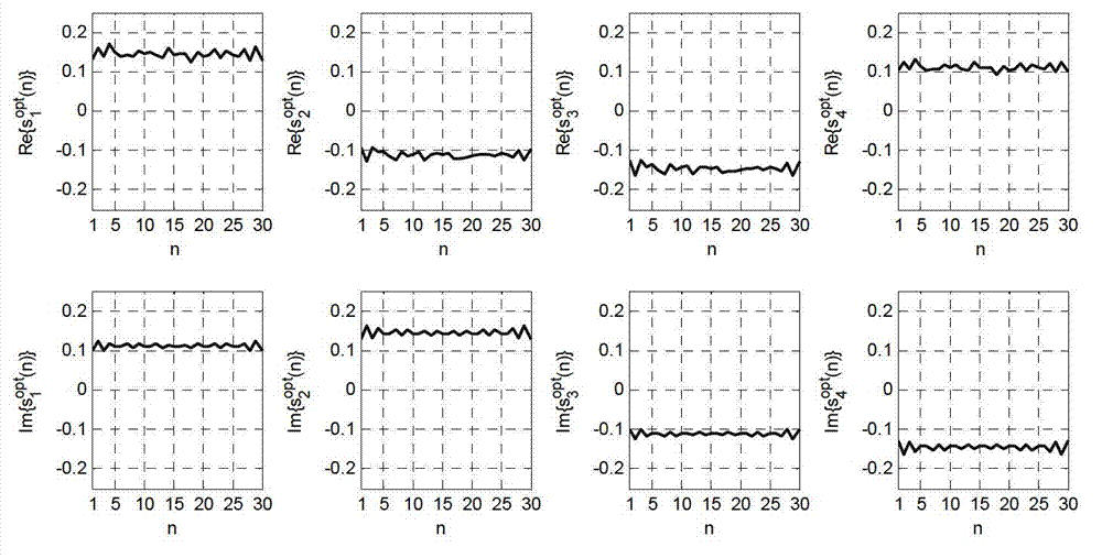
[0065] Let the carrier frequency f of the MIMO-OTH radar system be c = 10MHz, bandwidth B = 1500Hz, then the baseband signal frequency range of the transmitted signal waveform (pulse signal) is |f| The sampling frequency f s =1875Hz, from the relative signal frequency range [-W,W], get W=B / (2f s ) = 0.4. The usable working frequency band is, f 0 -B / 2≤f≤f 0 +B / 2, where f 0 =10MHz is the center frequency, and the pulse width of the signal is T=16ms, so the number of sampling points in the pulse is N=T f s =30. The angle of the target relative to the transmitting array and the receiving array is 30°, that is, θ t = θ r =30°, the total energy emitted is E 0 =4, the number of transmitting array elements (number of transmitting antennas) is M=4, and the number of receiving array elements (number of receiving antennas) is L=2. Obtain the radar waveform based on the DSP sequence of the present invention according to steps S101-601, refer to figure 1 , from sitting to ...

Embodiment 2

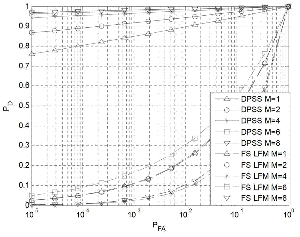
[0067] According to the set frequency bandwidth B=1500Hz, pulse width T=16ms, sampling frequency f s =1875Hz, determine the relative frequency bandwidth W=B / (2f s )=0.4, the number of sampling points in the pulse N=T f s =30, the angle θ of the target relative to the launch array t and the angle θ relative to the receiving array r Both are 30°, the total energy emitted is E 0 =4, the number of transmitting array elements (the number of transmitting antennas) is M, which is taken as 1, 2, 4, 6, and 8 in turn, and the number of receiving array elements (the number of receiving antennas) is L=2. Obtain 6 radar waveforms based on DSP sequences according to steps S101-601. Compared with the customary FS LFM waveforms of MIMO-OHT radar systems, the present invention has better detection performance, see figure 2 shown, where P FA Indicates the false alarm probability of the radar waveform, P D Indicates the monitoring probability of the waveform.


PUM


Abstract

The invention discloses a method for generating multi-input multi-output over-the-horizon (MIMO-OTH) radar waveforms based on digital signal processor (DSP) sequences, belonging to the technical field of MIMO-OTH radar and aiming to generate emission signals for an MIMO-OTH radar system. According to the technical problems that an MIMO-OTH radar has a narrower working frequency range and strong out-of-band interference, the method is characterized in that emission waveforms are constructed based on the DPS sequence and the waveform of each emission antenna is generated by conducting weighing summation on the same group of DPS sequences by adopting a group of different weights, therefore, waveforms of different emission antennas can be either orthorhombic or correlated with each other. In a circumstance that the total energy emitted by radar and other working parameters are constant, the detection probability of the MIMO-OTH radar system can be improved in a way of optimizing preset waveform weight parameters; and by adopting the method disclosed by the invention, the MIMO-OTH radar system achieves a good detection performance.

Description

technical field [0001] The invention belongs to the technical field of radar, in particular to a DSP sequence-based MIMO-OTH radar waveform generation method. Background technique [0002] Sky-wave over-the-horizon (OTH) radar is a radar system with ultra-long-distance target detection and information acquisition. The targets it detects are usually unknown and non-cooperative. It uses the ionosphere to reflect electromagnetic waves and look down. , to achieve target detection and parameter measurement. Multiple-input multiple-output (MIMO) radar is a radar system with multiple-input multiple-output characteristics. Compared with phased array radar, each transmitting antenna of MIMO radar can transmit any different waveforms, which has the benefit of waveform diversity. [0003] In recent years, with the gradual deepening of MIMO radar research, the advantages of MIMO have also been applied to radar systems. A system using the MIMO scheme for OTH radar is called MIMO-OTH ra...

Claims


Application Information

Patent Timeline
IPC IPC(8): G01S7/282
Inventor 汪霜玲何茜何子述骆恒
Owner UNIV OF ELECTRONICS SCI & TECH OF CHINA
Why Eureka
Try Eureka