Remote sensing image change detection method based on image fusion
A remote sensing image and change detection technology, which is applied in the field of image processing, can solve the problems of unfavorable change area contour and detail information, unsuitable analysis of SAR images, blurred edges of change areas, etc., achieve fast calculation speed, simple operation, and overcome noise sensitivity Effect
- Summary
- Abstract
- Description
- Claims
- Application Information
AI Technical Summary
Problems solved by technology
Method used
Image

Examples
Embodiment Construction
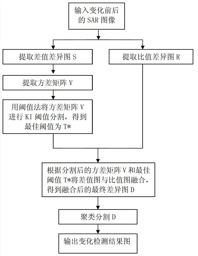
[0022] refer to figure 1 , the remote sensing image change detection method of image fusion of the present invention comprises the following steps:
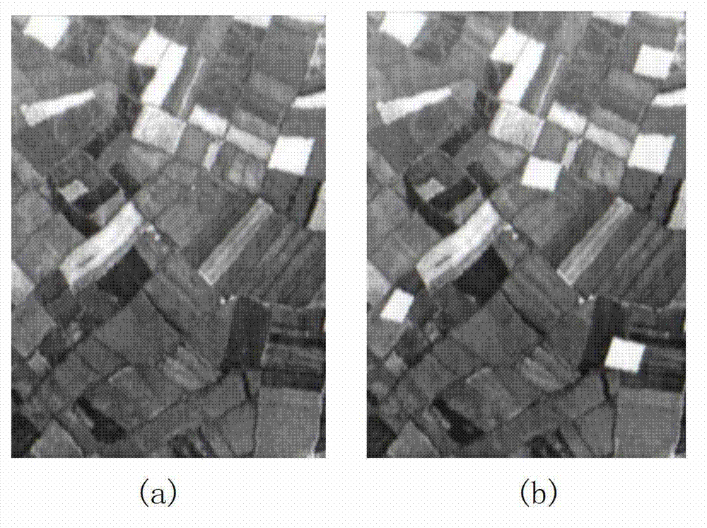
[0023] Step 1: Input the SAR image P before and after the change 1 and P 2 , calculate the difference between the corresponding pixel gray values of the two images, and normalize to obtain the gray matrix H of the difference image S R :
[0024] 1a) Calculate the input image P 1 The gray value of the pixel point (a, b) and the input image P 2 The difference Z of the gray value at the pixel point (a,b) S ab :
[0025] Z S ab = | P 1 ab - P 2 ab | ,
[0026] in, and are the input image P 1 The gray value of the pixel point (a, b) and the input image P 2 At the gray value of the pixel point (a, b), a, ...
PUM
 Abstract
Description
Claims
Application Information
 - Generate Ideas
- Intellectual Property
- Life Sciences
- Materials
- Tech Scout
- Unparalleled Data Quality
- Higher Quality Content
- 60% Fewer Hallucinations
Browse by: Latest US Patents, China's latest patents, Technical Efficacy Thesaurus, Application Domain, Technology Topic, Popular Technical Reports.
© 2025 PatSnap. All rights reserved.Legal|Privacy policy|Modern Slavery Act Transparency Statement|Sitemap|About US| Contact US: help@patsnap.com