Pneumatic damping high-capacity pay-off technology for flat wire

A pneumatic damping and large-capacity technology, applied to electrical components, circuits, conductor/cable insulation, etc., can solve the problems of low production efficiency and troublesome operation of the wire-releasing device, and achieve high production efficiency, low labor intensity, and release smooth line effect

Inactive Publication Date: 2013-03-13
无锡市梅达电工机械有限公司
View PDF5 Cites 3 Cited by
  • Summary
  • Abstract
  • Description
  • Claims
  • Application Information

AI Technical Summary

Problems solved by technology

[0005] Aiming at the disadvantages of troublesome operation and low production efficiency of the pay-off device in the above-mentioned existing production technology, the applicant provides a flat wire pneumatic damping large-capacity pay-off device, so that it can be used flexibly, the labor intensity of workers is low, and the production efficiency is high.

Method used


Image

  • Pneumatic damping high-capacity pay-off technology for flat wire
  • Pneumatic damping high-capacity pay-off technology for flat wire
  • Pneumatic damping high-capacity pay-off technology for flat wire

Examples


Embodiment Construction

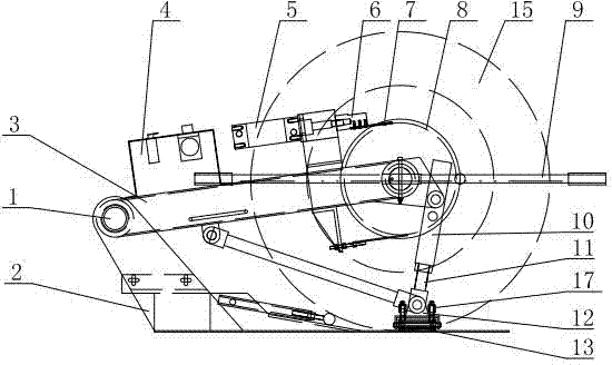
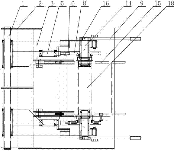
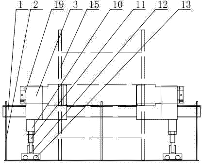
[0017] The specific implementation manner of the present invention will be described below in conjunction with the accompanying drawings.

[0018] Such as figure 1 , figure 2 and image 3 As shown, the flat wire pneumatic damping large-capacity pay-off device of the present embodiment includes a frame 2 on which a sliding shaft 1 is installed, and supporting devices are arranged at intervals on the ground on one side of the displacement frame 2; Arm 3, one end of the rotating arm 3 is sleeved on the slide shaft 1, and the other end is connected with the support device. The structure of the support device is: a support seat 12 is installed, a roller 13 is installed on the bottom of the support seat 12, and a compression spring 17 is installed on the roller 13. The support base 12 is connected with the screw rod 11, the screw rod 11 is covered with a support rod 10, and the support rod 10 has a plurality of holes connected with one end of the rotating arm 3; the rotating arm ...


PUM


Abstract

The invention relates to a pneumatic damping high-capacity pay-off device for a flat wire. The device comprises a frame which is provided with a sliding shaft. Supporting devices are arranged on the group on one side of the displacement frame at intervals. The device further comprises a rotary arm. One end of the rotary arm is sleeved on the sliding shaft while the other end of the rotary arm is connected with the supporting devices. The supporting device is structured by comprising a supporting base, wherein an idle wheel is installed at the bottom of the supporting base, a compression spring is installed on the idle wheel, a screw is connected to the supporting base, the screw is sleeved with a supporting rod, and the supporting rod is provided with a plurality of holes connected with one end of the rotary arm. An eccentric shaft is further installed on the rotary arm connected with the supporting device. A handle and a brake wheel which operate the eccentric shaft to rote are installed on the eccentric shaft. A pay-off disc is installed between a pair of supporting devices and is connected with the eccentric shaft. The rotary arm is further provided with a pneumatic control element, an air cylinder is further installed on the rotary arm on one side of the pneumatic control element, and an air cylinder head is connected with a brake belt matched in use with the brake wheel. The production efficiency is high.

Description

technical field [0001] The invention relates to enameled wire production equipment, in particular to a pneumatic damping large-capacity pay-off device suitable for flat wires. Background technique [0002] As the technology of enameled wire products becomes more and more mature, the requirements for enameled wire online production equipment are getting higher and higher. At present, in the process of producing flat wire enameled wire, winding flat wire enameled wire on the plate is the last process. [0003] The key to unwinding is to control the tension. When the tension is high, not only will the conductor be thinned, the surface of the wire will lose its luster, but it will also affect many properties of the enameled wire. From the appearance, the enameled wire coated with thinned wire has poor luster; from the performance point of view, the elongation, resilience, flexibility and thermal shock of the enameled wire are all affected. If the pay-off tension is too small, ...

Claims


Application Information

Patent Timeline
Patent Type & Authority Applications(China)
IPC IPC(8): H01B13/00H01B13/16
Inventor 谢晓鸣
Owner 无锡市梅达电工机械有限公司
Why Eureka
Try Eureka