Electronic control valve driving protective circuit of railway vehicles

A technology for driving protection circuits and rail vehicles. It is applied in the direction of protection against overcurrent, which can solve the problems of lack of monitoring and protection in the driving circuit of electro-pneumatic conversion valves, and achieve the effect of simple and clear structure and improved reliability.

Active Publication Date: 2013-03-13
NANJING CRRC PUZHEN HAITAI BRAKE EQUIP CO LTD
View PDF5 Cites 8 Cited by
  • Summary
  • Abstract
  • Description
  • Claims
  • Application Information

AI Technical Summary

Problems solved by technology

[0003] The technical problem to be solved by the present invention is to overcome the above-mentioned deficiencies in the prior art, provide a rail vehicle electric control valve drive protection circuit, and solve the problem of lack of monitoring and protection in the existing electropneumatic conversion valve drive circuit

Method used


Image

  • Electronic control valve driving protective circuit of railway vehicles

Examples


Embodiment Construction

[0013] In order to make the purpose, technical solutions and advantages of the embodiments of the present invention clearer, the technical solutions in the embodiments of the present invention will be clearly and completely described below in conjunction with the drawings in the embodiments of the present invention. Obviously, the described embodiments It is a part of embodiments of the present invention, but not all embodiments. Based on the embodiments of the present invention, all other embodiments obtained by persons of ordinary skill in the art without creative efforts fall within the protection scope of the present invention. It should be noted that the drawings are all in very simplified form and use imprecise ratios, which are only used to facilitate and clearly assist the purpose of illustrating the embodiments of the present invention.

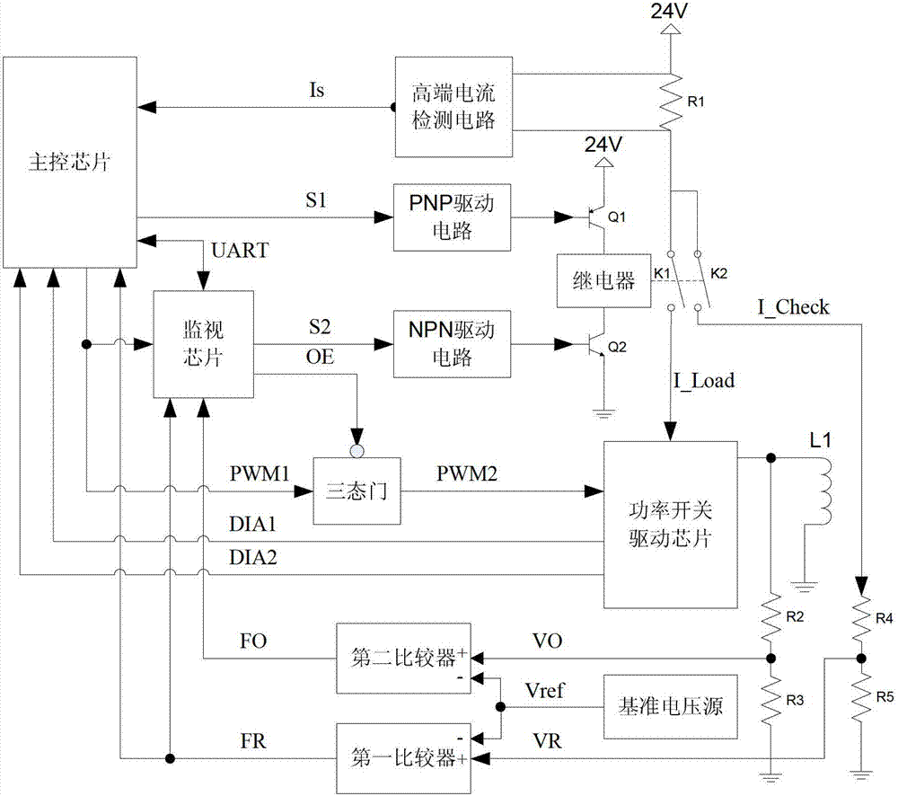
[0014] Such as figure 1 As shown, the rail vehicle electric control valve drive protection circuit of the embodiment of the presen...


PUM


Abstract

An electronic control valve driving protective circuit of railway vehicles is mainly formed by a main control chip, a monitoring chip, a power switch driving chip, a relay, a three-state gate, a comparator, a reference voltage source, a high-end current detection circuit and the like. The main control chip is mainly responsible for driving control of a valve, the monitoring chip is mainly responsible for monitoring circuit states at each level of the driving circuit, and the main control chip and the monitoring chip jointly control a driving return circuit. The main control chip and the monitoring chip switch information through a serial communication interface. The electronic control valve driving protective circuit solves the problem in the existing electronic control valve driving return circuit. The single monitoring chip is used for conducting status surveillance and protection on the driving return circuit of an electro-pneumatic changeover valve, states of the driving return circuit are fed back to the main control chip, the monitoring chip can locate fault points of the driving return circuit, fault safety guidance can be achieved, and relevant protection procedures can be carried out.

Description

technical field [0001] The invention relates to a drive protection circuit for an electric control valve of a rail vehicle, belonging to the technical field of subway brake control systems. Background technique [0002] Subway electro-pneumatic switching valves include anti-skid valves and EP valves. The drive circuit of electro-pneumatic switching valves in existing domestic subway brake controllers has the following disadvantages: 1. The drive of electro-pneumatic valves only has output feedback detection and lacks protection functions; 2. When the drive circuit fails, the fault point cannot be accurately located, and it is not easy to achieve fail-safe guidance. Contents of the invention [0003] The technical problem to be solved by the present invention is to overcome the above-mentioned deficiencies in the prior art, provide a rail vehicle electric control valve drive protection circuit, and solve the problem of lack of monitoring and protection in the existing elect...

Claims


Application Information

Patent Timeline
Patent Type & Authority Applications(China)
IPC IPC(8): H02H3/08
Inventor 孙卫兵杨俊刘寅虎杨正专
Owner NANJING CRRC PUZHEN HAITAI BRAKE EQUIP CO LTD
Why Eureka
Try Eureka