micro speaker

A technology of micro-speaker and voice coil, applied in the direction of sensors, electrical components, etc., can solve the problems of shortening the service life of micro-speakers, reducing the reliability of micro-speakers, poor electrical connection of micro-speakers, etc. Effect

Active Publication Date: 2015-10-28
GOERTEK INC
View PDF5 Cites 0 Cited by
  • Summary
  • Abstract
  • Description
  • Claims
  • Application Information

AI Technical Summary

Problems solved by technology

[0003] In the prior art, the voice coil lead wire of the micro-speaker is usually a tap of the wire for winding the voice coil. Since the wire for winding the voice coil is usually a thin enameled wire, the toughness of the wire is poor. It is easy to cause the breakage of the voice coil lead, resulting in poor electrical connection of the micro-speaker, which seriously reduces the reliability of the micro-speaker and greatly shortens the service life of the micro-speaker

Method used


Image

  • micro speaker
  • micro speaker
  • micro speaker

Examples


Embodiment 1

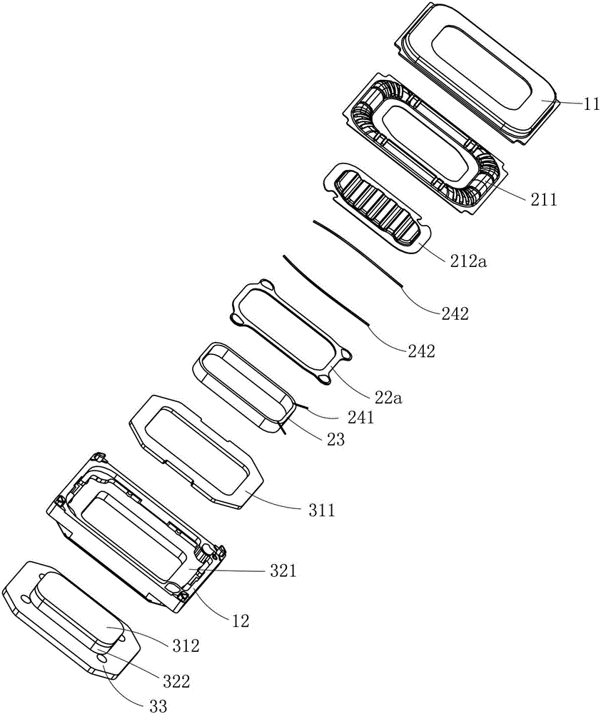
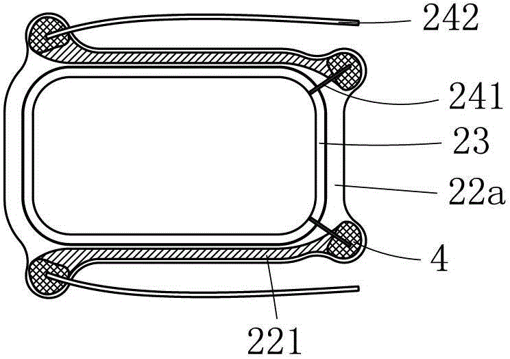
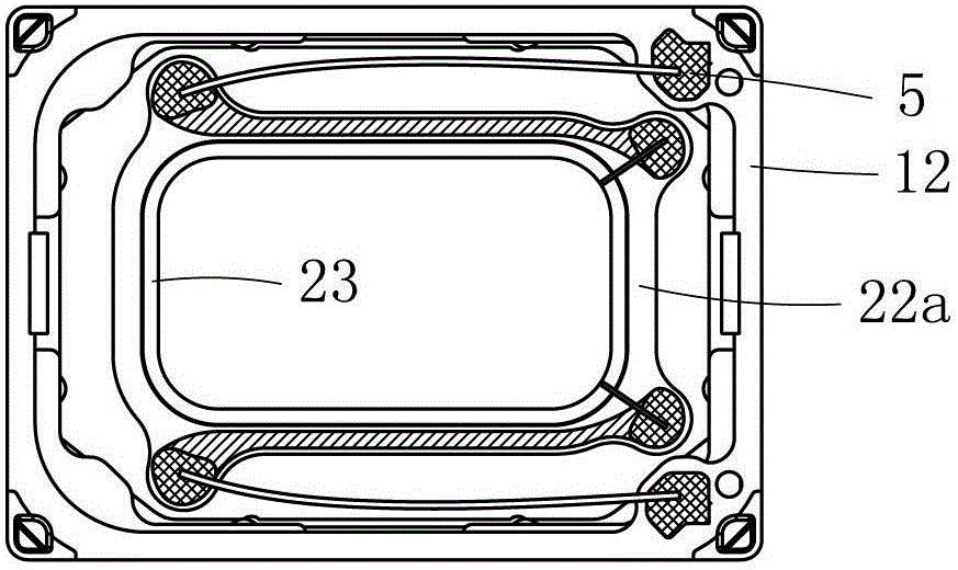
[0030] Such as figure 1 , figure 2 and image 3 Commonly shown, a micro-speaker includes a housing 12 and a front cover 11 that is buckled together with the housing 12. The voice coil outlet terminal 5 is provided on the housing 12, and the cavity surrounded by the housing 12 and the front cover 11 accommodates The vibration system and the magnetic circuit system, the vibration system includes a diaphragm and a voice coil 23, the diaphragm includes a ring-shaped outer diaphragm 211 and an inner diaphragm 212a located inside the outer diaphragm 211, the lead wire of the voice coil 23 includes an integral body with the voice coil 23 The voice coil body lead wire 241, the voice coil body lead wire 241 is connected to the voice coil extension lead wire 242 through a conductive component, and the material of the voice coil extension lead wire 242 is a conductive material with better toughness than the material of the voice coil body lead wire 241, such as brocade wire, The voice...

Embodiment 2

[0035] Such as Figure 4 , Figure 5 and Figure 6 Commonly shown, the main difference between this embodiment and Example 1 is that the connecting piece 22b is a hard plastic sheet, and the four corners of the connecting piece 22b are all formed into pads 4 through conductive treatment, and the conductive treatment can be used on the connecting piece 22b. The corners of the connecting piece 22b are plated with conductive material to form a pad 4, or a metal sheet is bonded to the corner of the connecting piece 22b as the pad 4, and the lead wire 241 of the voice coil body and the extended lead wire 242 of the voice coil are connected to the same pad at the same time. 4.

[0036] In this embodiment, the four corners of the connecting piece 22b are all provided with the structure of the pads 4, and only two corners on the same short side of the connecting piece 22b may be provided with the welding pads 4. Coil body lead wire 241 and voice coil extension lead wire 242 are con...

Embodiment 3

[0039] Such as Figure 5 As shown, the main difference between this embodiment and the above-mentioned embodiments is that the conductive component includes a pad 4 disposed on the edge of the inner diaphragm 212b for electrically connecting the voice coil body lead 241 and the voice coil extension lead 242.

[0040] The inner diaphragm 212b is rectangular and made of hard plastic. The edges of the four corners of the inner diaphragm 212b are all formed with conductive pads 4. The conductive treatment can be done by coating the corners of the inner diaphragm 212b with conductive coating. The material is used to form the pad 4, or a metal sheet is bonded to the corner of the inner diaphragm 212b as the pad 4, and the lead wire 241 of the voice coil body and the extended lead wire 242 of the voice coil are connected to the same pad 4 at the same time.

[0041] In this embodiment, the four corners of the inner diaphragm 212b are all provided with pads 4, and only the two corners ...


PUM


Abstract

The invention discloses a micro loudspeaker, and relates to the technical field of electroacoustic products. The micro loudspeaker comprises a housing and a front cover combined with the housing, wherein a vibrating system and a magnetic circuit system are accommodated in a cavity defined by the housing and the front cover; the vibrating system comprises a vibrating membrane and a voice coil; lead wires of the voice coil comprise a voice coil body lead wire integral with the voice coil; and the voice coil body lead wire is connected with a voice coil extension lead wire through a conducting component; the voice coil extension lead wire is made of a material the tenacity of which is better than that of the material of the voice coil body lead wire. By adopting the micro loudspeaker, the technical problem that the existing micro loudspeaker voice coil lead wire is easily broken is solved. The voice coil lead wire of the micro loudspeaker disclosed by the invention is good in tenacity, good in strength, and not easily broken, thus improving the reliability of the micro loudspeaker, and prolonging the service of the micro loudspeaker.

Description

technical field [0001] The invention relates to the technical field of electroacoustic products, in particular to a micro speaker. Background technique [0002] With the rapid development of portable electronic products, micro-speakers, which are important acoustic devices in portable electronic products, have been widely used. The micro-speaker usually includes a vibration system and a magnetic circuit system housed in the casing. The vibration system includes a diaphragm and a voice coil arranged in sequence. The voice coil is connected to the voice coil outlet terminal on the casing through the voice coil lead to connect the external circuit. The working principle of the micro-speaker is to feed the voice coil with alternating current, and under the action of the magnetic field generated by the magnetic circuit system, it will reciprocate relative to the magnetic circuit system. The voice coil drives the diaphragm to vibrate together, and the diaphragm drives the air to ...

Claims


Application Information

Patent Timeline
Patent Type & Authority Patents(China)
IPC IPC(8): H04R9/06H04R9/02
Inventor 刘春发蔡晓东葛连山徐同雁
Owner GOERTEK INC
Why Eureka
Try Eureka