
Electronic circutt board

An electronic circuit board, electrical connection technology, applied in the direction of circuit, printed circuit, printed circuit, etc., can solve the problem of the overall impedance of the printed circuit board

Inactive Publication Date: 2013-03-13
STAR TECH INC
View PDF9 Cites 4 Cited by
  • Summary
  • Abstract
  • Description
  • Claims
  • Application Information

AI Technical Summary

Problems solved by technology

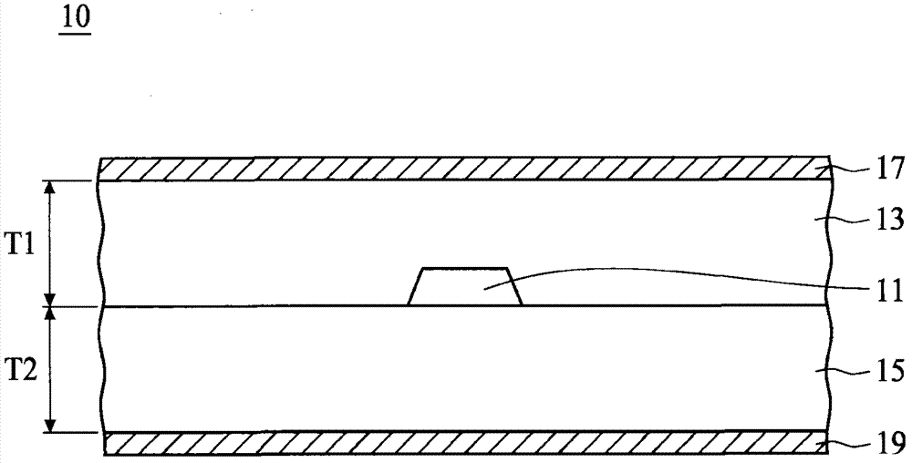
However, the disadvantage of this prior art is that the overall impedance of the printed circuit board depends on the thickness (T1, T2) of the two dielectric layers 13, 15, that is, it is affected by the manufacturing specifications and the environment.

Method used


Image

  • Electronic circutt board
  • Electronic circutt board
  • Electronic circutt board

Examples


Embodiment Construction

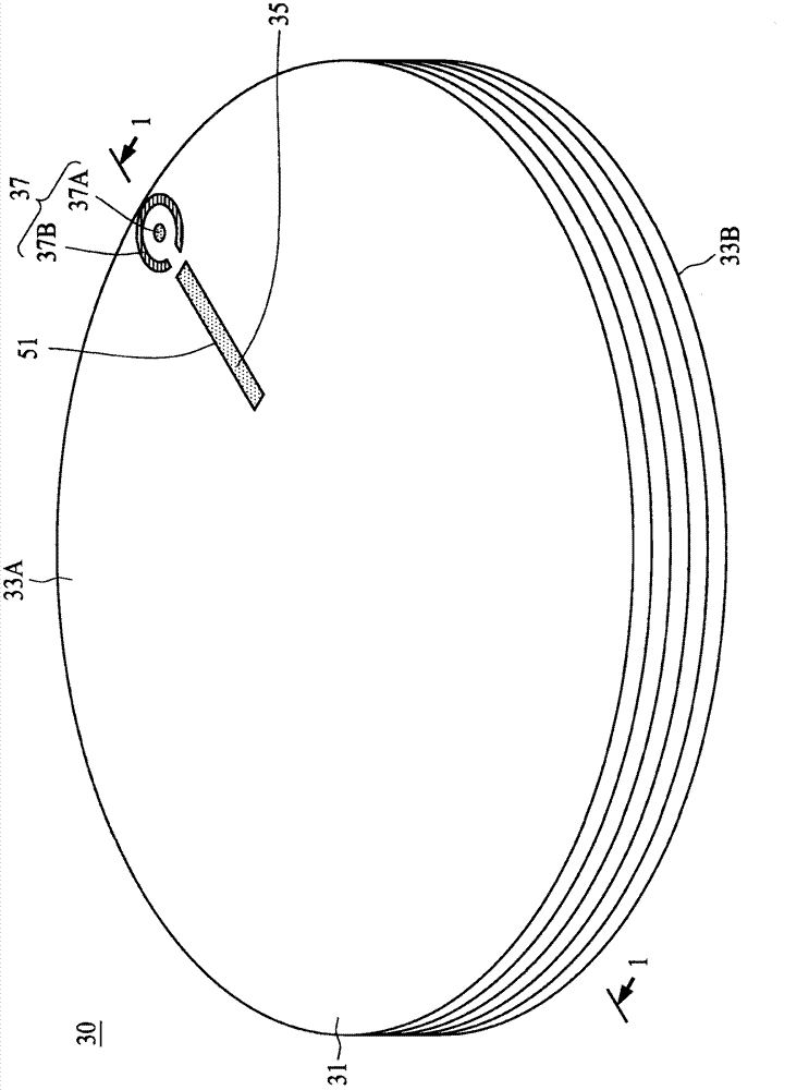
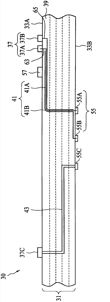
[0061] figure 2 It is a top view illustrating a high-frequency electronic circuit board 30 according to an embodiment of the present invention, image 3 for along figure 2 Sectional view of the 1-1 section line. In one embodiment of the present invention, the electronic circuit board 30 includes a laminated structure 31 with an upper surface 33A and a lower surface 33B, wherein the upper surface 33A has a groove 35; a high-frequency coaxial line 41, disposed in the groove 35 ; and a protection layer 51 filling the groove 35 .

[0062] In one embodiment of the present invention, the high frequency coaxial cable 41 is configured to transmit a high frequency signal, one end of the high frequency coaxial cable 41 is connected to a composite structure 37, and the other end is connected to another composite structure 55 . In an embodiment of the present invention, the composite structure 37 includes a signal pad 37A and a ground pad 37B, and the ground pad 37B substantially su...


PUM


Abstract

In one embodiment of the present invention, a high frequency circuit board includes a laminate having a top surface with a groove; a semi-rigid cable positioned in the groove of the laminate; and a passivation layer filling the groove; wherein the semi-rigid cable is configured to transmit a high frequency signal, and the semi-rigid cable comprises a central conductor, an outer conductor, and an insulating layer between the central conductor and the outer conductor.

Description

technical field [0001] The present invention relates to an electronic circuit board, in particular to a high-frequency electronic circuit board configured with a high-frequency coaxial line capable of transmitting high-frequency signals. Background technique [0002] Electronic components, such as cell phones, use circuits to transmit high and low frequency signals. Integrated high-frequency and low-frequency circuits generally use hybrid substrates, where low-frequency components are placed on FR4, and high-frequency components are placed on ceramic substrates or substrates with low dielectric loss. Although both high frequency and low frequency signals can be transmitted on the same substrate; however, a single metal line must be used for low frequency signals and multiple metal lines (forming waveguide structures such as microstrip lines) for high frequency signals. [0003] figure 1 It is an existing electronic circuit board 10 . The electronic circuit board 10 includ...

Claims


Application Information

Patent Timeline
IPC IPC(8): H05K1/02
CPCH05K2201/09809H05K2201/09027H05K1/0237H05K2201/10356H05K2201/09036H05K3/103H05K1/11H05K1/02H01P3/06
Inventor 刘俊良
Owner STAR TECH INC
Learn More