A modular phased-array antenna

A phased array antenna, modular technology, applied in the direction of modular array, antenna, resonant antenna, etc., can solve the problems of upper limit of feasible size of network unit, limitation of data throughput, limitation of antenna range, etc.

Inactive Publication Date: 2013-03-13
尼奥・麦克马努斯 +1
View PDF6 Cites 4 Cited by
  • Summary
  • Abstract
  • Description
  • Claims
  • Application Information

AI Technical Summary

Problems solved by technology

As a result of this limitation, the data throughput from active users is limited; and for a given operating power output, the range of the antenna is limited, thereby placing an upper limit on the feasible size of the network element

Method used


Image

  • A modular phased-array antenna
  • A modular phased-array antenna
  • A modular phased-array antenna

Examples


Embodiment Construction

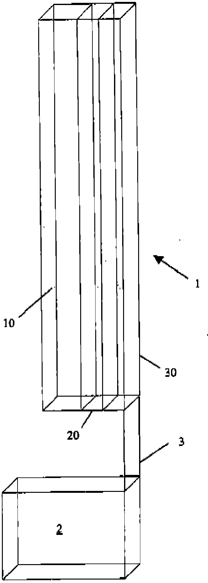
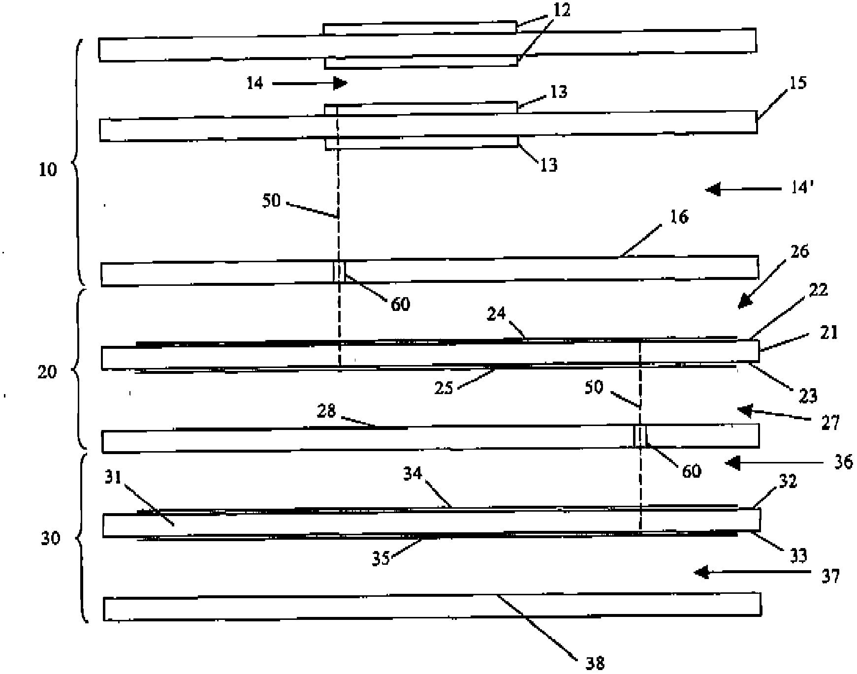
[0042] according to figure 1 , 2 and 3, the antenna 1 includes three modules: a patch array module 10 , a matching network module 20 , and a beamforming network module 30 . These modules are housed in metal housings (not shown) when in use. Typically, the housing will include a microwave transparent window positioned opposite the patch array module. The antenna is linked to a network base station 2 via a communication link 3 .

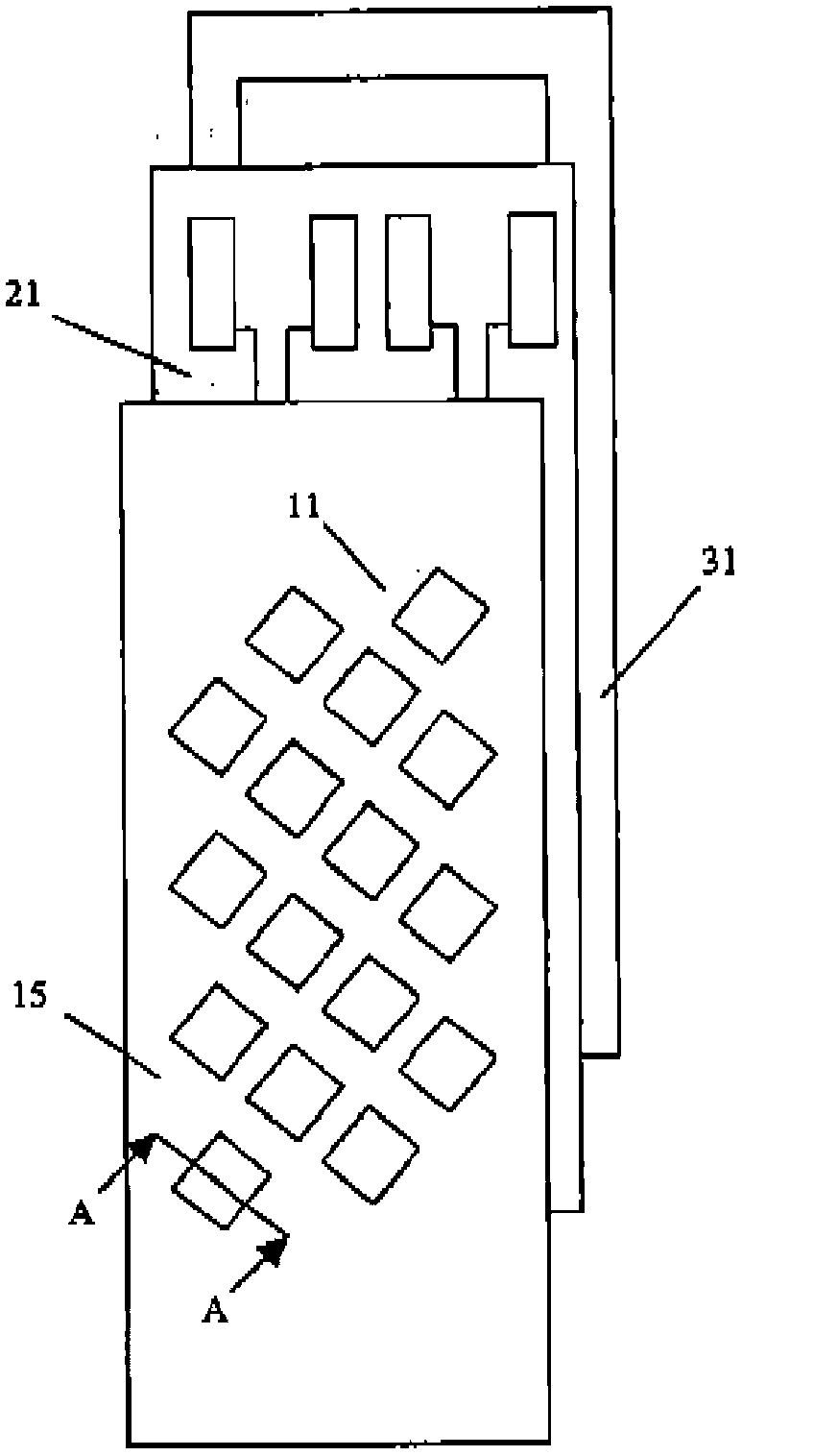
[0043] The patch array module 10 includes a first insulating base 15 and a plurality of patch units arranged in an offset periodic array. The patch array includes N columns of M patch units; the embodiment shown in the figure includes a 4x4 patch array (NxM). Adjacent columns of the patch unit 11 are separated by a distance equivalent to half of the antenna operating wavelength λ; the M patch units in each column should be separated so that the distance is long enough to minimize the mutual coupling effect, and the distance is sufficient Small to...


PUM


Abstract

A modular phased-array antenna including a beam-forming network module, a patch array module, and a matching network module interconnecting the beam-forming network module and the patch array module. The beam- forming network includes suspended stripline passive hybrid and crossover elements configured in a Butler Matrix formation interconnected with transceiver antenna patches via the matching network module which in turn comprises suspended stripline phased-matched tracks and a plurality of oppositely polarised matching elements.

Description

technical field [0001] The present invention relates generally to antennas for cellular telecommunication networks. More specifically, the present invention relates to phased array antennas for multi-sector network scenarios. Background technique [0002] Such as Figure 11 As shown, a conventional network antenna 73 is located at the junction of three adjacent network elements 70 . The network unit 71 includes an active network user, that is to say a user who is someone operating a mobile telecommunication handset or any other network compatible telecommunication terminal within the unit 71 . [0003] Here, the network antenna 73 transmits a signal to the user, but to do so must be broadcast throughout the unit 71, thereby radiating power to an area centered on the network antenna 73 and spanning an angle of 120 degrees. In a network element, the broadcast power acts as an interference signal to other users. The mobile telecommunication handset, or other similar active t...

Claims


Application Information

Patent Timeline
Patent Type & Authority Applications(China)
IPC IPC(8): H01Q1/24H01Q9/04H01Q21/00H01Q21/06H01Q25/00H01Q3/40
CPCH01Q1/246H01Q21/061H01Q3/40H01Q9/0414H01Q21/0087H01Q25/00H01Q21/0081H01Q21/065H01Q1/38H01Q3/26H01Q21/0025
Inventor 尼奥·麦克马努斯伊恩·阿特金森
Owner 尼奥・麦克马努斯
Why Eureka
Try Eureka