Vacuum pouring method of ingot casting and heat-generating agent feeding barrel for ingot casting and vacuum chamber for pouring

A technology for vacuum pouring and feeding barrels, which is applied in the field of heating agent feeding barrels and vacuum chambers for pouring. It can solve the problems of low yield of ingots and unsatisfactory effects of heating agents, etc., so as to improve the yield and save the need for cutting risers. Process, the effect of reducing waiting time

Active Publication Date: 2013-03-20
秦皇岛核诚镍业有限公司
View PDF5 Cites 5 Cited by
  • Summary
  • Abstract
  • Description
  • Claims
  • Application Information

AI Technical Summary

Problems solved by technology

[0003] The object of the present invention is to provide an ingot with a high yield of ingot and extremely energy Vacuum pouring method for casting ingots to maximize the effect of exothermic agents, barrels for exothermic agents used, and vacuum chambers for pouring

Method used


Image

  • Vacuum pouring method of ingot casting and heat-generating agent feeding barrel for ingot casting and vacuum chamber for pouring
  • Vacuum pouring method of ingot casting and heat-generating agent feeding barrel for ingot casting and vacuum chamber for pouring
  • Vacuum pouring method of ingot casting and heat-generating agent feeding barrel for ingot casting and vacuum chamber for pouring

Examples


Embodiment 1

[0028] In Example 1, 2 tons of ingots were poured, the material was N04400, and the exothermic agent was a carbon-free exothermic agent.

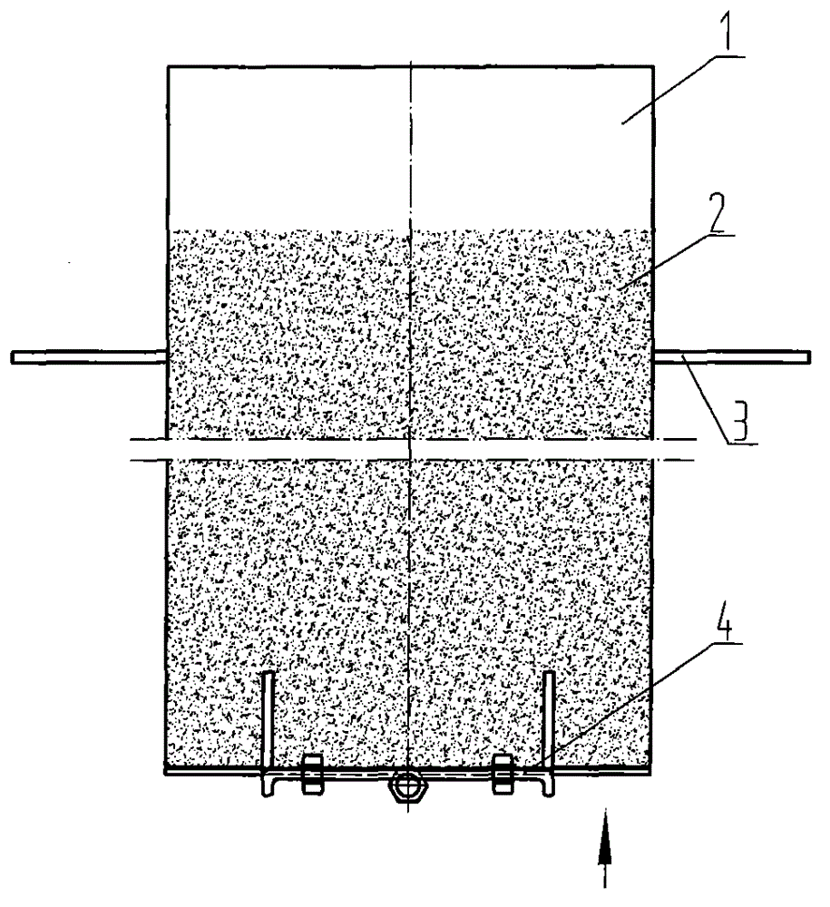
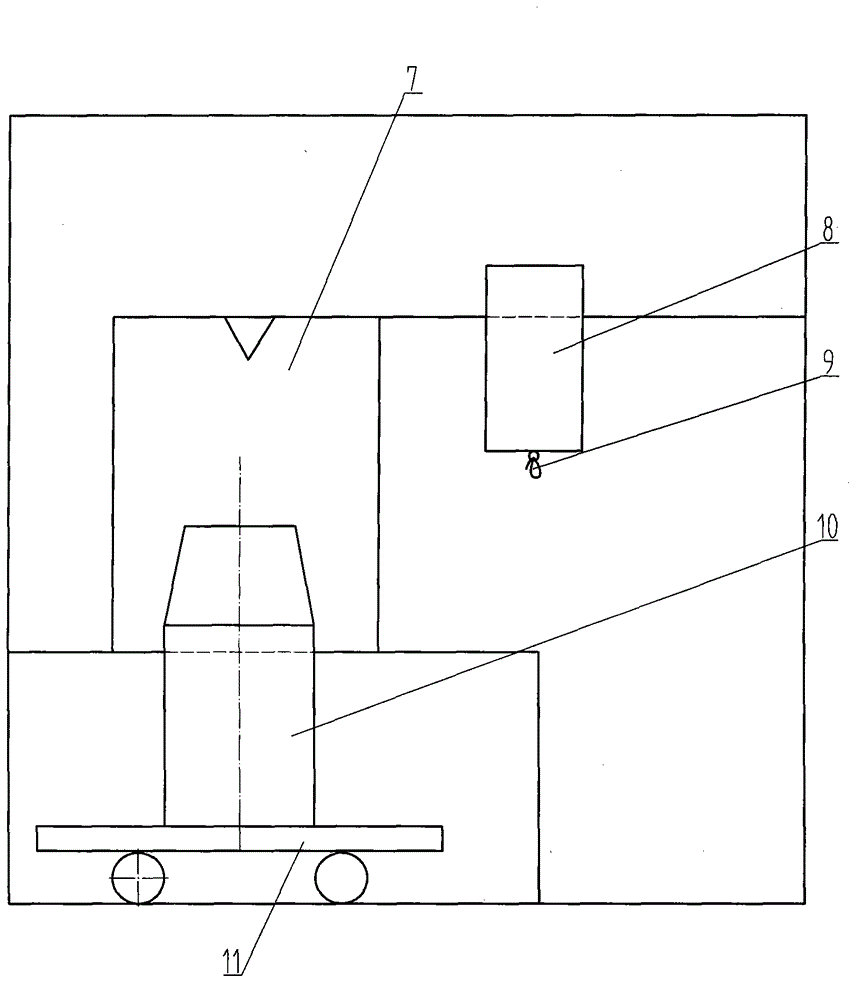
[0029] Vacuum pouring is carried out as follows: tie the bottom door 5 of the feeding barrel 8 with an asbestos rope, and close the bottom door 5; put the whole bag of heating agent into the feeding barrel 8, and put the feeding barrel into the chamber of the vacuum chamber. The cavity is fixed; the raw material is vacuum smelted in the crucible 7, and when the smelting of the raw material in the crucible is completed, it is poured into the ingot mold 10, and the vacuum chamber is broken for 20 seconds after the pouring is completed, so that the pressure of the vacuum chamber reaches about 10,000 Pa. Move the ingot mold 10 directly below the feeding barrel 8, the high temperature of the ingot mold itself will melt the asbestos rope tied to the floor door 5, the floor door 5 is opened, and the exothermic agent 2 enters the riser 12 of the ste...

Embodiment 2

[0030] Example 2 Ingot 0.2 tons, the material is N04400, the exothermic agent is carbon-free, and the exothermic agent breaks the vacuum chamber for 15 seconds, and the rest is the same as in Example 1. The obtained ingot riser ratio was 12%.

Embodiment 3

[0031] Example 3 Cast 10 tons of ingots, the material is N04400, the exothermic agent is carbon-free, and the exothermic agent breaks the vacuum chamber for 20 seconds, and the rest are the same as in Example 1. The resulting ingot riser ratio was 10%.

[0032] Table 1: Compared with the ordinary method for vacuum casting by adopting the method of the present invention to carry out vacuum casting, the ingot riser accounts for the weight ratio comparison table of the ingot:

[0033]


PUM


Abstract

The invention provides a vacuum pouring method of ingot casting and a heat-generating agent feeding barrel for ingot casting and a vacuum chamber for pouring. The shortcoming that during vacuum poring in the prior art, a heat-generating agent adding method enables ingot casting yields to be low, the effect of the added heat-generating agent is not ideal is overcome. The method comprises at least two steps, namely pouring liquid steel into an ingot mould in a vacuum mode and adding the heat-generating agent into a riser. After the liquid steel is poured into the ingot mould, the vacuum chamber is broken immediately. When the pressure of the vacuum chamber reaches 8000-12000 Pa, the heat-generating agent is immediately added into the riser in the vacuum chamber. The feeding barrel is arranged inside the vacuum chamber. The feeding barrel comprises a barrel body. A bottom plate door which turns downwards is arranged on the bottom of the barrel body. The bottom plate door is closed through a hot melting component. According to the method, the feeding barrel and the vacuum chamber, the ingot casting yields are high, and the effect of the heat-generating agent can be achieved greatly.

Description

technical field [0001] The invention relates to a vacuum pouring method for casting ingots, a heating agent feeding barrel and a pouring vacuum chamber, in particular to a vacuum pouring method for corrosion-resistant alloys, a heating agent feeding barrel and a pouring vacuum chamber. Background technique [0002] When the molten steel is vacuum poured, when the molten steel is poured, an exothermic agent needs to be added into the riser to prevent premature solidification of the ingot riser and strengthen the feeding effect of the riser. At present, the commonly used method is to open the vacuum chamber after the molten steel is poured from the crucible into the ingot mold, remove the ingot mold from the vacuum chamber, and then pour the exothermic agent into the riser. This process takes about 5 minutes. When the volume of the ingot is relatively small, such as pouring an ingot of less than 10 tons, due to the small volume of the ingot, the heat at the top of the riser of...

Claims


Application Information

Patent Timeline
Patent Type & Authority Applications(China)
IPC IPC(8): B22D7/12B22D18/06
Inventor 王明家李艳美牛清海
Owner 秦皇岛核诚镍业有限公司
Why Eureka
Try Eureka