

Cutter wear mechanism analysis method
A tool wear and mechanism analysis technology, which is applied in the direction of manufacturing tools, metal processing machinery parts, measuring/indicating equipment, etc., can solve the problems of long time consumption and high cost, and achieve the effect of low cost and wide application
Inactive Publication Date: 2013-03-20
ZHEJIANG OCEAN UNIV
View PDF5 Cites 10 Cited by
- Summary
- Abstract
- Description
- Claims
- Application Information
AI Technical Summary
Problems solved by technology
[0004] The problem to be solved by the present invention is that it takes a long time and high cost to analyze the mechanism of tool wear with existing instruments.
Method used
View moreImage
Smart ImageViewing Examples


Examples
Embodiment
[0023] Cutting simulation conditions:
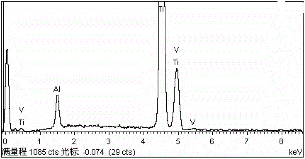
[0024] Workpiece material: titanium alloy TC4, solution aging in heat treatment state;
Login to View More PUM
 Abstract
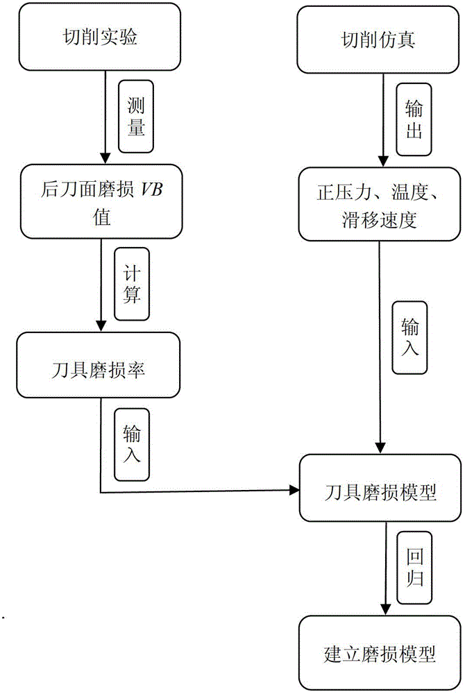
The invention discloses a cutter wear mechanism analysis method, belonging to the technical field of metal cutting machining. The analysis of a cutter wear mechanism is realized by building a novel cutter wear model and by means of a finite element method. The cutter wear model is as shown by an accompanying drawing, wherein the rear cutter surface wear value VB of a cutter can be measured through an experiment, the wear rate of the cutter is further obtained, other variables can be obtained through cutting simulation, and finally the corresponding numerical values of abrasive wear, adhesive wear and diffusive wear can be measured through a multiple regression method. Since the finite element simulation method is used for analyzing the wear mechanism of the cutter, the cutter wear mechanism analysis method has the advantages that the method is simple and feasible and the cost is lower.
Description
technical field [0001] The invention relates to a tool wear mechanism analysis method, which belongs to the technical field of metal cutting. Background technique [0002] Tool wear has an important impact on the metal cutting process. In order to control and optimize the metal cutting process and obtain the best cutting speed under certain cutting conditions, it is necessary to master the tool wear mechanism. Tool wear in metal cutting is a cumulative and irreversible process, which is quite complicated. Common causes of wear include abrasive wear, adhesive wear, and diffusion wear. At present, there is no good method to analyze the mechanism of tool wear. It can only be analyzed by means of scanning electron microscope and energy spectrum analysis. It is not only time-consuming and costly, but also easy to cause oxidation of the specimen and affect the analysis results. Therefore, it is an urgent problem to be solved. . Contents of the invention [0003] The purpose o...
Claims
Login to View More Application Information
Patent Timeline
 Patent Type & AuthorityApplications(China)
IPC IPC(8): B23Q17/09
Inventor袁跃峰
OwnerZHEJIANG OCEAN UNIV