Shaft locating mechanism

A technology of shaft positioning and positioning body, applied in mechanical equipment, connecting components and other directions, can solve the problems of complex structure, installation and manufacturing process, waste of raw materials, inappropriateness, etc., and achieve the effect of low manufacturing and installation cost, saving raw materials, and simple process

Inactive Publication Date: 2013-03-20
SUZHOU BLUE KING MACHINE TOOL TECH CO LTD
View PDF11 Cites 2 Cited by
  • Summary
  • Abstract
  • Description
  • Claims
  • Application Information

AI Technical Summary

Problems solved by technology

[0002] As we all know, in the field of traditional machinery manufacturing, when shaft mechanical parts are required to neither allow rotation nor axial movement after installation, the The general method is to make step shoulders on the shaft or install nuts, retaining rings and other parts to limit the axial movement of the shaft, and use keys and pins to limit the circumferential rotation of the shaft. Obviously, this type of shaft positioning mechanism has a structure, The defects of complex installation and manufacturing process, the serious waste of raw materials and the high cost of parts manufacturing, in addition, this type of shaft positioning mechanism is generally difficult to disassemble and assemble, so it is not suitable for use in occasions that require frequent disassembly and assembly

Method used


Image

  • Shaft locating mechanism
  • Shaft locating mechanism
  • Shaft locating mechanism

Examples


Embodiment Construction

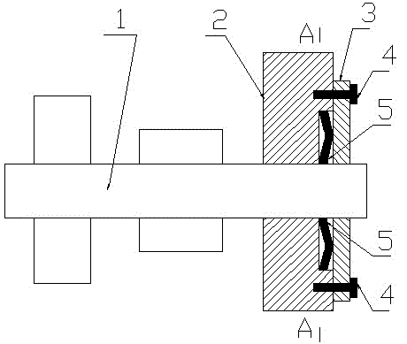
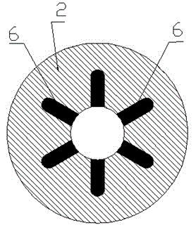
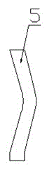
[0011] A shaft positioning mechanism, which includes a shaft (1), a positioning body (2), a pressure plate (3), a bolt (4), and a bow-shaped spring piece (5), and is characterized in that: the shaft (1) is installed on the positioning body (2 In the hole on the positioning body (2), there are long slots (6) uniformly distributed radially around the hole of the positioning body (2), and a bow-shaped spring piece (5) is arranged in each long slot (6). The arched spring sheet (5) described above is arcuate in shape, and in a free state, the arched back of the arched spring sheet (5) is higher than the outside of the long groove (6), and the bolt (4) is used outside the orifice of the positioning body (2). A pressing plate (3) is installed and fixed, and said pressing plate (3) forms an extrusion tendency to the back of the arched spring leaf (5).


PUM


Abstract

A shaft locating mechanism is characterized in that a shaft is arranged in a hole in a locating body, long grooves which are evenly distributed in a radial circumference mode are arranged on the periphery of the hole in the locating body, an arch-shaped spring piece is arranged in each long groove, the arch-shaped spring piece is in an arch shape, the arch back of the arch-shaped spring piece is higher than the outside of each long groove on a free state, a pressing plate is fixedly arranged on the outer side of the hole in the locating body through a bolt, and the pressing plate tends to extrude the arch back of the arch-shaped spring piece. The shaft locating mechanism has the advantages of being simple in technique, and low in manufacturing and mounting cost, raw materials are saved, assembling and disassembling are quick and convenient.

Description

technical field [0001] The invention relates to a shaft positioning mechanism, in particular to a shaft positioning mechanism which does not allow rotation and axial movement after the shaft is installed and fixed. Background technique [0002] As we all know, in the field of traditional machinery manufacturing, when the shaft mechanical parts are required to be neither allowed to rotate nor allow axial movement after installation, the general method adopted is to make a step shoulder on the shaft or install a nut, stopper, etc. Rings and other parts are used to limit the axial movement of the shaft, and keys and pins are used to limit the circumferential rotation of the shaft. This type of shaft positioning mechanism obviously has defects in structure, installation, and complicated manufacturing processes, and there is a serious waste of raw materials and parts manufacturing. The defect of high cost, in addition, this type of shaft positioning mechanism is generally diffi...

Claims


Application Information

Patent Timeline
Patent Type & Authority Applications(China)
IPC IPC(8): F16B21/10
Inventor 孙生强
Owner SUZHOU BLUE KING MACHINE TOOL TECH CO LTD
Why Eureka
Try Eureka