Method for three-dimensional passive positioning of targets by air moving platform

A passive positioning and motion platform technology, applied in the field of three-dimensional passive positioning of targets and three-dimensional passive positioning of targets by aerial motion platforms, can solve the problems of coherent processing at the receiving end, inability to locate, low positioning accuracy, etc. The effect of estimation accuracy, not easy to be detected, not easy to detect

Inactive Publication Date: 2013-03-20
XIDIAN UNIV
View PDF2 Cites 30 Cited by
  • Summary
  • Abstract
  • Description
  • Claims
  • Application Information

AI Technical Summary

Problems solved by technology

The track where the distance difference remains constant is a hyperboloid, and the position of the moving platform can be determined according to the intersection of multiple hyperboloids, but this system is also only for positioning the aerial moving platform equipped with a receiver, and cannot The target of the receiver is positioned, and the Roland C remote positioning system is realized by using the time difference positioning system
[0007] (4) Frequency difference positioning method, which uses the Doppler frequency difference information FDOA between the incoming wave signals to reach the sensors, and uses this to determine the position of the target. The disadvantage of this method is that each station needs to move relative to the target , general frequency difference positioning is difficult to

Method used


Image

  • Method for three-dimensional passive positioning of targets by air moving platform
  • Method for three-dimensional passive positioning of targets by air moving platform
  • Method for three-dimensional passive positioning of targets by air moving platform

Examples


Embodiment Construction

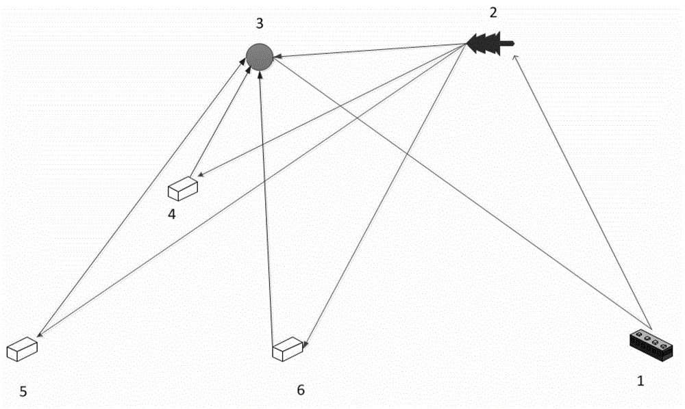
[0033] refer to figure 1 , the main station 3 used in the embodiment of the present invention is an aerial motion platform, the electromagnetic wave required for the detection of the radiation target by the transmitting station 1, and the target 2 is the target to be positioned, and the main station 3 is responsible for receiving the direct wave radiated by the transmitting station and the scattering of the target 2 to be positioned For echo, auxiliary station 4, auxiliary station 5, and auxiliary station 6 are three receiving stations on the ground respectively.

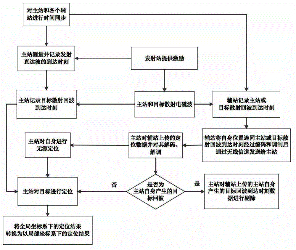
[0034] refer to figure 2 , the specific implementation steps of this embodiment are as follows:

[0035] Step 1, time synchronization is performed on the master station 3, the slave station 4, the slave station 5, and the slave station 6.

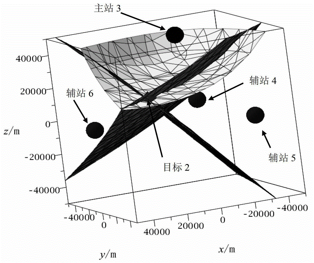
[0036] Such as figure 1 As shown, the present invention locates the master station 3 itself through the arrival time of the data uploaded by the three auxiliary stations to t...


PUM


Abstract

The invention discloses a method for three-dimensional passive positioning of targets by an air moving platform. The method mainly solves the problem that air moving platforms in the prior art can not conduct passive positioning on air moving platforms and targets simultaneously. The method comprises that 1) time synchronization is conducted on a master station which receives target scattering echoes and all auxiliary stations; 2) a radar transmitting station radiates targets and detects required electromagnetic waves; 3) the master station records the arrival time of transmitted directed waves and records the arrival time of target scattering echoes, and all auxiliary stations record the arrival time of scattering echoes of the master station or the arrival time of scattering echoes of targets; 4) auxiliary stations transmit position information of auxiliary stations and the arrival time information of scattering echoes of the master station or the arrival time information of scattering echoes of targets to the master station; 5) the master station positions the master station and targets; and 6) positions of targets in a global coordinate system are converted into positions in a local coordinate system. The method has the advantages of being high in positioning precision and high in hiding performance and can be used for three-dimensional passive positioning of targets by the air moving platform.

Description

technical field [0001] The invention belongs to the technical field of target positioning, and in particular relates to a three-dimensional passive positioning method for a target, which can be used for three-dimensional passive positioning of a target by an aerial motion platform. Background technique [0002] At present, the air movement platform generally adopts the active working method to locate the target. Because it has its own radiation source, it is easy to be discovered by the opponent and carry out effective strikes. In addition, the position of the air movement platform itself often needs to be obtained with the help of other positioning systems such as GPS. , which makes the aerial motion platform lose the ability to locate itself when other positioning systems fail, so that it cannot obtain the position information of the target relative to itself. Therefore, it is of great practical significance and application prospect to perform passive positioning on the ae...

Claims


Application Information

Patent Timeline
IPC IPC(8): G01S5/16
Inventor 陈伯孝雷文英杨明磊朱伟米闯冯凯凯
Owner XIDIAN UNIV
Why Eureka
Try Eureka