Optical cable connector for device access and optical cable installing and sealing component thereof

A technology for optical cable connectors and sealing components, applied in the coupling of optical waveguides, fiber mechanical structures, etc., can solve the problems of high cost, complicated sealing operation methods, unsuitable for efficient and fast installation, etc., to achieve fast sealing installation and simple structure , the effect of low production cost

Active Publication Date: 2013-03-20
中航光电(广东)有限公司
View PDF3 Cites 6 Cited by
  • Summary
  • Abstract
  • Description
  • Claims
  • Application Information

AI Technical Summary

Problems solved by technology

These schemes, due to a certain degree of investment (equipment sealing design, shell processing or custom molds), are relatively expensive, and the sealing operation methods of some schemes are relatively complicated, which is not suitable for efficient and fast installation.
[0003] In addition, the interface direction of communication equipment is usually parallel to the ground of the house, and the existing optical cable connectors are all connectors with straight-line outlets at the tail. It is also kept parallel to the ground of the house, but the communication tower is usually built o

Method used


Image

  • Optical cable connector for device access and optical cable installing and sealing component thereof
  • Optical cable connector for device access and optical cable installing and sealing component thereof

Examples


Embodiment Construction

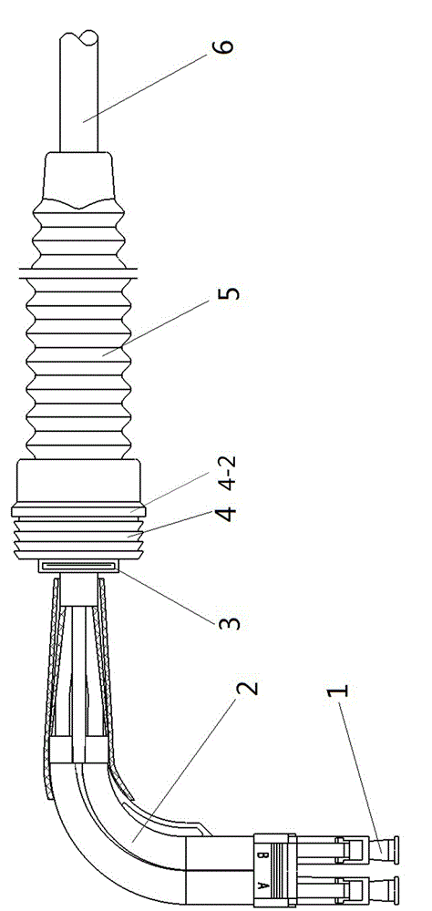
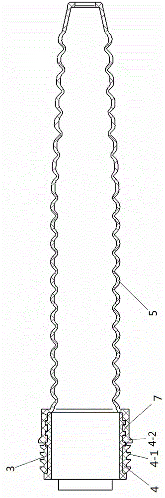
[0021] Implementation example of optical cable connector for equipment access Figure 1~2 Shown: It includes an optical cable 6, a DLC plug 1 connected to the rear end of the optical cable 6, and an optical cable installation sealing assembly arranged in front of the DLC plug. The optical cable installation and sealing assembly includes a supporting sleeve 3, an optical cable elbow sheath 2, and a sealing sleeve 4 made of flexible material and sleeved on the supporting sleeve 3 and axially restricted by an axial limiting structure. In this embodiment The middle sealing sleeve is a rubber sleeve, and the back end of the sealing sleeve is integrally provided with a corrugated tube 5 for protecting the optical cable. The corrugated tube, the optical cable elbow sheath 2 and the supporting sleeve all have inner holes for the optical cable 6 to pass through, and the routing directions of the inner holes of the optical cable elbow sheath 2 are perpendicular to each other. The rear e...


PUM


Abstract

The invention relates to an optical cable connector for device access and an optical installing and sealing component of the optical cable connector for device access. The optical cable installing and sealing component comprises a supporting cover and coordinating potions of mounting holes, wherein the supporting cover extends forward and backward in a radial direction, the coordinating portions of mounting holes are arranged in the periphery of the supporting cover, and the apertures of the coordinating portions of the mounting holes are smaller than the apertures of the corresponding mounting holes of the connector arranged on the panels of the device. Seal covers made of soft materials are sleeved on the coordinating portions through axial limiting structures, and one soft tooth capable of being transformed telescopically or a plurality of annular soft teeth capable of being transformed telescopically along an axial direction in intervals is/are arranged integrally on the seal cover. During the process that the soft teeth are merged from back to front into a corresponding mounting hole of the connector, the soft teeth are squeezed in a radial direction to deform by the cooperation of the supporting cover and the hole wall of the mounting hole of the corresponding connector, and fill a gap between the supporting cover and the mounting hole of the connector when the cooperating portions of the installing holes are completely merged in the installing holes of the connector, and therefore a seal is formed. The invention provides an optical installing and sealing component, wherein the optical installing and sealing component is simple in structure, low in cost, and can achieve fast sealing installation with a corresponding panel.

Description

Technical field [0001] The present invention relates to the technical field of optical cable transmission, in particular to an optical cable connector for equipment access and an optical cable installation sealing assembly thereof. Background technique [0002] The outdoor communication base station includes communication equipment and a communication tower set on the top of the corresponding house. The peripheral cover of the communication equipment is provided with a communication panel. The communication equipment and the communication tower need to be connected by optical cables, and the optical cables and communication equipment are connected through optical cable connectors. The optical cable connector generally includes a DLC plug and an optical cable. When in use, the DLC plug is connected to the interface on the communication device, and the optical cable is led out from the corresponding opening of the device panel. In the prior art, in order to ensure the communication...

Claims


Application Information

Patent Timeline
IPC IPC(8): G02B6/44G02B6/38
Inventor 姚琦李小卫
Owner 中航光电(广东)有限公司
Why Eureka
Try Eureka