Method for reducing mask board splicing errors

A mask plate and error technology, which is applied to the photographic process of the pattern surface, the original for photomechanical processing, optics, etc., to achieve the effects of eliminating distortion processing, ensuring consistency, and improving yield

Inactive Publication Date: 2013-03-20
BOE TECH GRP CO LTD
View PDF6 Cites 18 Cited by
  • Summary
  • Abstract
  • Description
  • Claims
  • Application Information

AI Technical Summary

Problems solved by technology

[0003] Using mask splicing, multiple step-by-step exposure technology can produce large-sized panels, but when mask splicing, two adjacent masks have the same exposure pattern area, forming a splicing area, such as figure 1 As shown, the first reticle 1 and the second reticle 2 are spliced, and the adjacent edge thereof is the splicing area 3, and the exposure pattern corresponding to the splicing area 3 has one exposure more than one exposure, so the splicing The graphics in area 3 will be different from those in non-stitched areas, such as ...

Method used


Image

  • Method for reducing mask board splicing errors
  • Method for reducing mask board splicing errors
  • Method for reducing mask board splicing errors

Examples


Embodiment Construction

[0022] The specific implementation manners of the present invention will be further described in detail below in conjunction with the accompanying drawings and embodiments. The following examples are used to illustrate the present invention, but are not intended to limit the scope of the present invention.

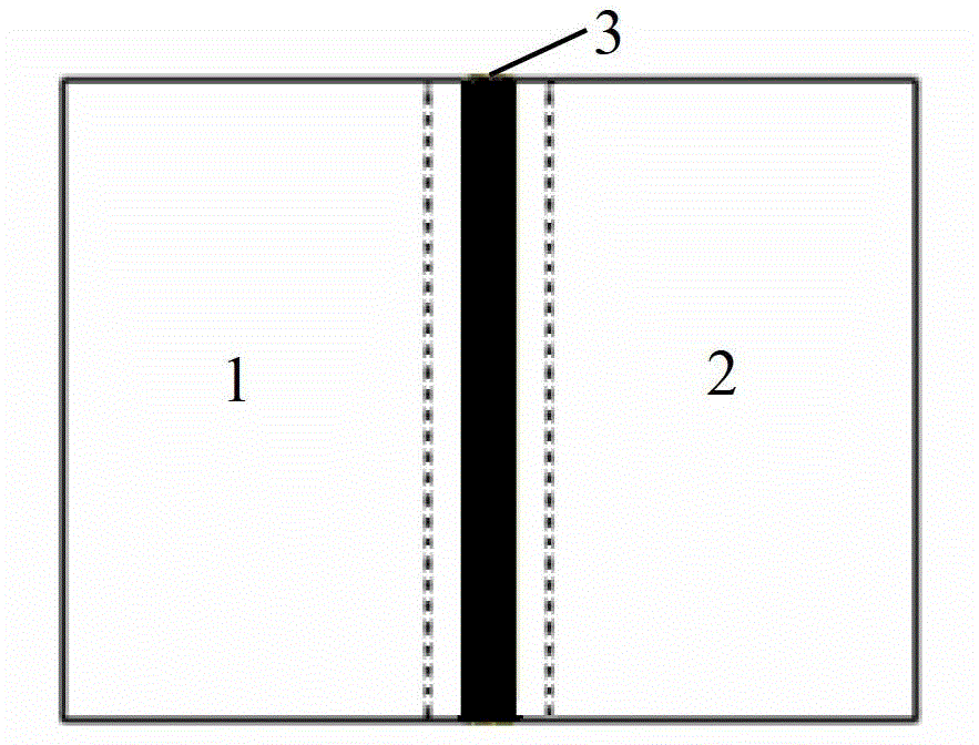
[0023] The method for reducing the splicing error of the mask plate provided in this embodiment is to reversely check all the patterns on the mask plate according to the result of the pattern formed by etching the exposure pattern on the splicing area of ​​two adjacent masks after repeated exposure. Structural compensation is performed on the exposure pattern of the spliced ​​region. The so-called reverse compensation is to perform structural compensation opposite to the result of the graph.

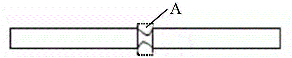
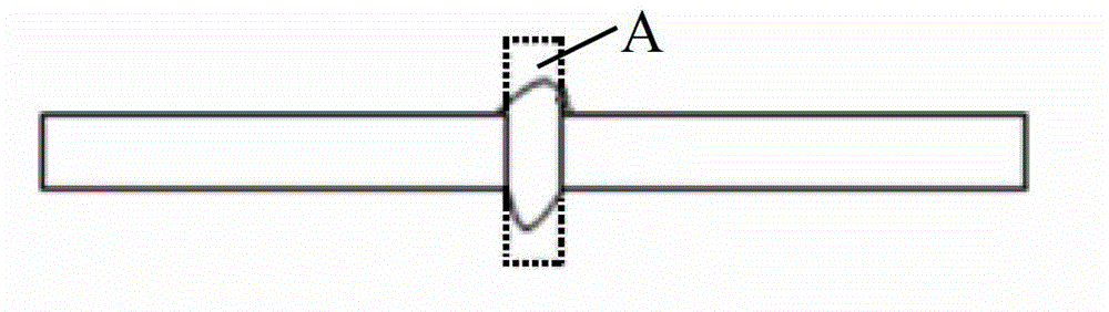
[0024] Specifically, for figure 2 The phenomenon that the etched pattern A of the exposure pattern on the splicing area 3 formed after repeated exposure is narrower than the patte...


PUM


Abstract

The invention discloses a method for reducing mask board splicing errors. According to the result of a graph formed by etching an exposed graph after repeated exposure on a splicing area of two adjacent mask boards, the structural compensation is carried on the exposed graph on the splicing area on the mask boards reversely. By utilizing the method, the distortion treatment to the exposed graph at the splicing area caused by repeated exposure and process deviation can be eliminated through compensation design of the mask boards, the consistency of an etched graph at the splicing area and an etched graph at a non-splicing area is ensured, and the yield of products is increased.

Description

technical field [0001] The invention relates to the field of display technology, in particular to a method for reducing mask splicing errors. Background technique [0002] As the panel size of TFT-LCD continues to increase, various TFT-LCD manufacturers have invested in high-generation production lines in order to produce larger-sized panels. Due to the increase in panel size, it is necessary to use several smaller-sized masks for multiple step-by-step exposures to form larger-sized panels, and then realize the functions of large-sized panels through certain designs and arrangements. [0003] Using mask splicing, multiple step-by-step exposure technology can produce large-sized panels, but when mask splicing, two adjacent masks have the same exposure pattern area, forming a splicing area, such as figure 1 As shown, the first reticle 1 and the second reticle 2 are spliced, and the adjacent edge thereof is the splicing area 3, and the exposure pattern corresponding to the spl...

Claims


Application Information

Patent Timeline
IPC IPC(8): G03F1/38
Inventor 赵利军林允植
Owner BOE TECH GRP CO LTD
Why Eureka
Try Eureka