PET-CT equipment and travel mechanism of barrier

A technology of moving mechanisms and barriers, applied in the field of medical devices, can solve problems such as difficulties, increased support system design, poor scanning image fusion effect, etc.

Active Publication Date: 2013-03-27
SHENYANG INTELLIGENT NEUCLEAR MEDICAL TECH CO LTD
View PDF6 Cites 12 Cited by
  • Summary
  • Abstract
  • Description
  • Claims
  • Application Information

AI Technical Summary

Problems solved by technology

From the perspective of mechanical structure realization, it is obviously very difficult to ensure the consistency of the position of the object before and after the movement and the high accuracy of repeated positioning at any point over a long distance; in addition, when the switching distance is large, the length and extension of the bed board itself The distance going out will be relatively long, forming a longer cantilever, which will have an extremely adverse effect on the bearing capacity o...

Method used


Image

  • PET-CT equipment and travel mechanism of barrier
  • PET-CT equipment and travel mechanism of barrier
  • PET-CT equipment and travel mechanism of barrier

Examples


Embodiment Construction

[0049] In order to enable those skilled in the art to better understand the technical solutions of the present invention, the present invention will be further described in detail below in conjunction with the accompanying drawings and specific embodiments.

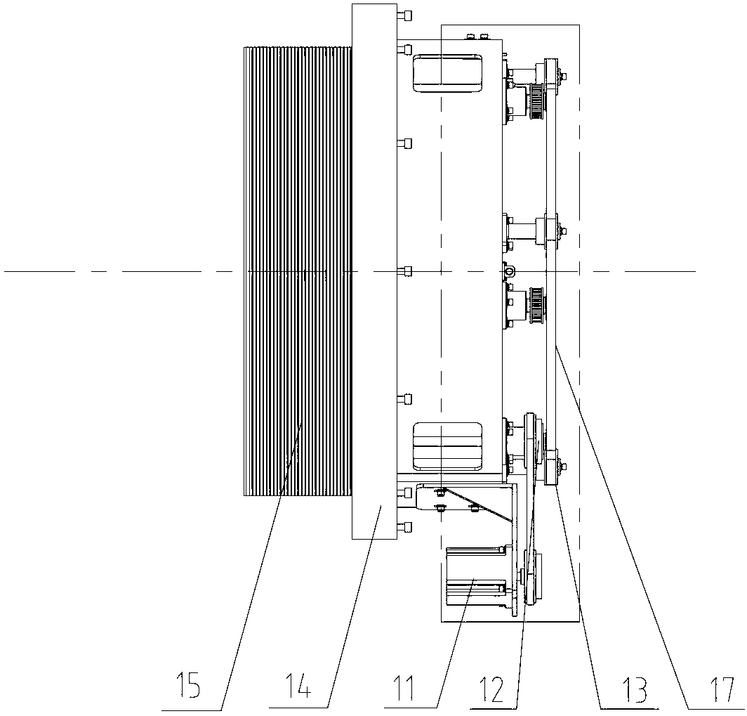
[0050] Please refer to Figure 5-7 , Figure 5 It is a structural front view of the first embodiment of the moving mechanism of the grill provided by the present invention; Image 6 for Figure 5 left view of Figure 7 for Figure 5 A schematic diagram of the three-dimensional structure.

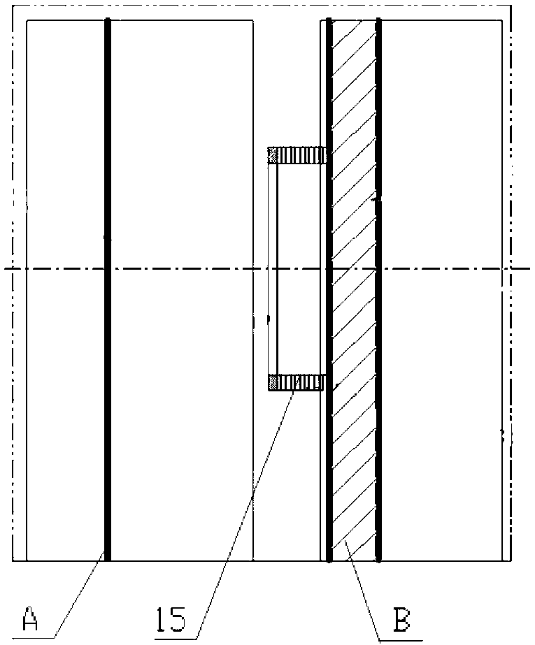
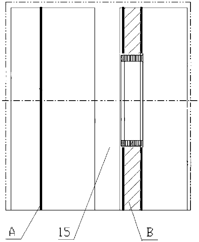
[0051] The moving mechanism of the barrier 20 is used to drive the barrier 20 to move in the axial direction, and the movement of the barrier 20 can complete the switching of 2D or 3D imaging modes, and the specific function can be understood by referring to the background art.

[0052] The moving mechanism includes a frame 21 for supporting the grille 20, and a guide rail 22 arranged on the frame 21 and extending in the axial dire...


PUM


Abstract

The invention discloses PET-CT equipment and a travel mechanism of a barrier, wherein the disclosed travel mechanism comprises a frame for supporting the barrier and a guide rail arranged on the frame and extending in the axial direction; the barrier is capable of moving along the guide rail; the travel mechanism further comprises a driving device for driving the barrier to move; and the driving device is directly arranged on the frame. The driving device of the travel mechanism is directly arranged on the frame; as a result, the driving device can be basically located in the space between the solid part of the frame and the guide rail without increasing the axial length of the whole travel mechanism; and the axial length of the whole travel mechanism can be basically controlled to be the sum of the axial lengths of the frame and the guide rail so that the axial space is thoroughly utilized. Compared with the scheme of arranging the driving device in the axial direction on the basis of the end portion of the guide rail in the background art, apparently, the scheme of directly arranging the driving device on the frame is capable of obviously reducing the integrated length of the travel mechanism; therefore, the distance between the PET machine and the CT machine is reduced.

Description

technical field [0001] The invention relates to the technical field of medical devices, in particular to a PET-CT device and a moving mechanism of a barrier. Background technique [0002] PET-CT equipment is a device that integrates a PET machine and a CT machine. The PET machine scan provides detailed molecular information such as the function and metabolism of the lesion, while the CT machine scan can provide the precise anatomical location of the lesion, and one imaging can obtain whole body information. The tomographic images in all directions are characterized by sensitivity, accuracy, specificity and precise positioning, so as to achieve the purpose of early detection of lesions and diagnosis of diseases. [0003] Please refer to Figure 1-2 , figure 1 It is a schematic diagram of the structure of the barrier located inside the PET-CT equipment; figure 2 for figure 1 Schematic diagram of the axial movement of the middle grille to another position. [0004] fig...

Claims


Application Information

Patent Timeline
IPC IPC(8): A61B6/03
Inventor 杜卫刚梁国栋杨波高岩田胜辉赵国涛王云琴王清
Owner SHENYANG INTELLIGENT NEUCLEAR MEDICAL TECH CO LTD
Why Eureka
Try Eureka