Medical system and medical control method

A technology of medical system and control department, applied in the field of medical system, can solve problems such as time-consuming waiting for treatment and difficulty in efficient medical behavior

Inactive Publication Date: 2011-10-12
OLYMPUS MEDICAL SYST CORP
View PDF6 Cites 4 Cited by
  • Summary
  • Abstract
  • Description
  • Claims
  • Application Information

AI Technical Summary

Problems solved by technology

[0015] In this case, it is expected that there will be problems in that it takes time to wait for treatment or treatment, and it is difficult to perform efficient medical actions

Method used


Image

  • Medical system and medical control method
  • Medical system and medical control method
  • Medical system and medical control method

Examples


no. 1 Embodiment approach

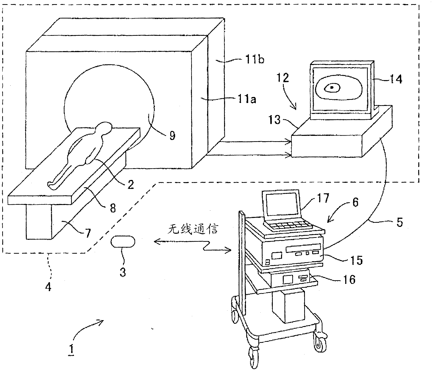
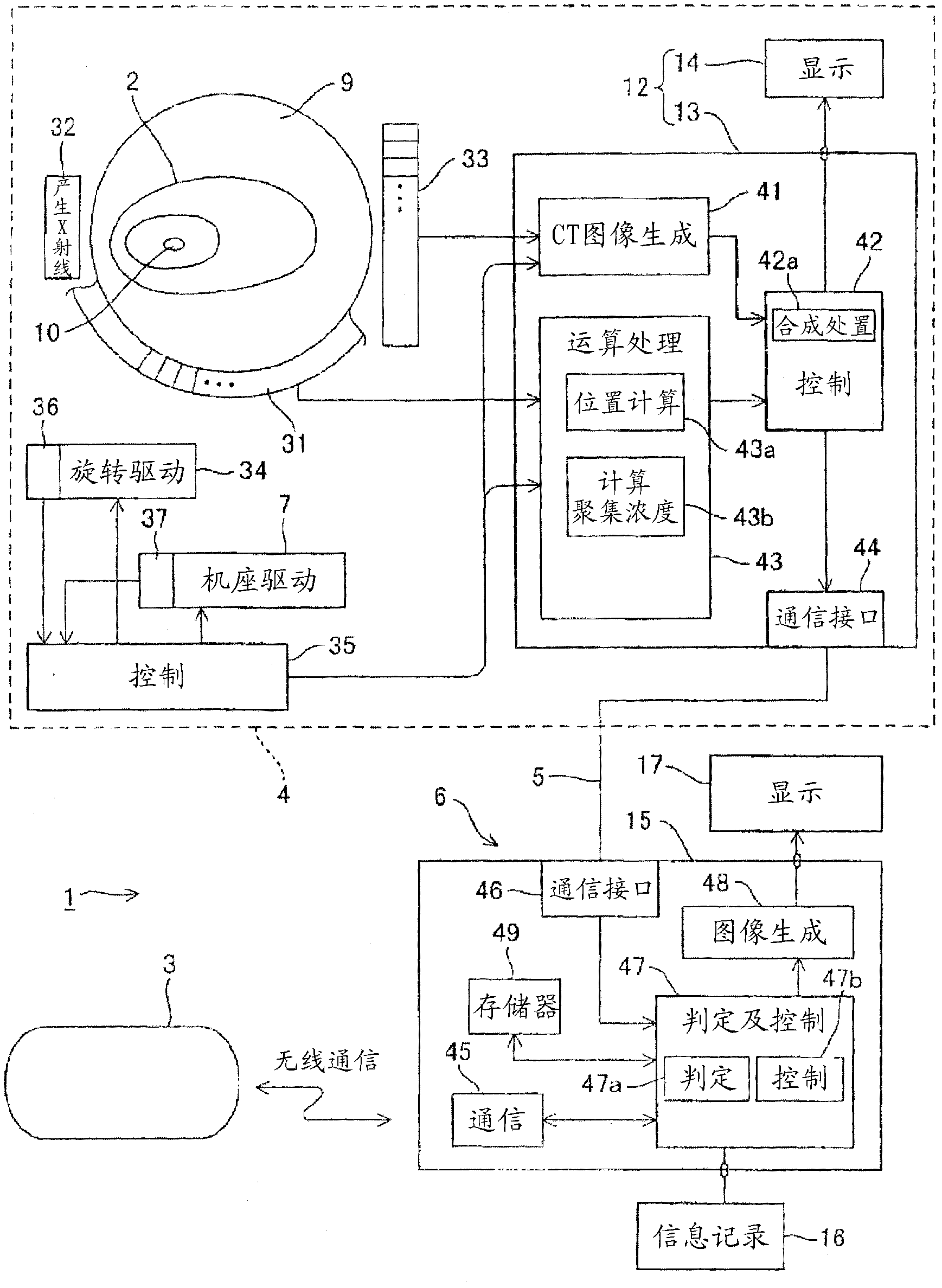
[0037] figure 1 The medical system 1 according to the first embodiment of the present invention is shown. This embodiment has an in vitro medical device and an in vivo medical device. The in vitro medical device is arranged outside a living body and has a first detection unit for The living body acquires the second living body information second detecting unit. In addition, the in-vivo medical device has an operation unit that performs a predetermined operation based on the first biological information received from the external medical device, and a control unit that controls the operation unit based on the second biological information. It will be described in detail below.

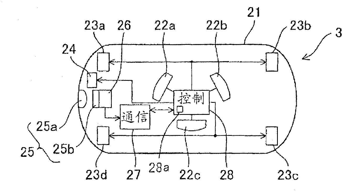
[0038] Such as figure 1 As shown, the medical system 1 has a capsule medical device 3 as an in-vivo medical device, and the capsule medical device 3 is inserted from the mouth of the patient 2 or placed in the patient 2 to perform predetermined operations.

[0039] In addition, this medical system 1...

no. 2 Embodiment approach

[0169] Figure 10 The configuration of a capsule medical device 3C according to the second embodiment of the present invention is shown in an operation explanatory diagram. This embodiment is in figure 1 Adopted in the medical system1 Figure 10A capsule medical device 3C is shown instead of the capsule medical device 3 .

[0170] This capsule medical device 3C is provided with a clamp 61 that can freely protrude from the outer container 21 and be detached from the capsule medical device 3C.

[0171] Then, when the capsule control unit 28 receives the control signal from the information processing device 6, it controls to drive the clip drive unit 62 so that the clip 61 protrudes from the capsule medical device 3C. The gripper 61 is formed of, for example, a shape-memory substance, and when the gripper drive unit 62 is driven by the capsule control unit 28 to generate heat, the gripper 61 in the contracted state will expand as Figure 10 Protrudes from the clamp housing to...

no. 3 Embodiment approach

[0191] Figure 11 The configuration of the capsule medical device 3D according to the third embodiment of the present invention is shown with an operation explanatory diagram.

[0192] The capsule medical device 3D of this embodiment is in the capsule medical device 3C of the second embodiment, as Figure 11 The illustrated biopsy forceps (biopsy treatment instrument) 66 that directly collects a living tissue 2a is provided as an operating part instead of a marking unit that marks a specific part of the living tissue 2a.

[0193] The capsule control unit 28 of the present embodiment has the same control function as that of the first embodiment, and also has the function of the biopsy forceps control unit 67 for collecting tissue ( Biopsy) actions are controlled.

[0194] The operation of this embodiment is different from the operation of the first embodiment or the medical control method. Image 6 The contents of step S1 to step S11 are the same. The differences are descri...


PUM


Abstract

A PET-CT device (4) disposed outside the body of a patient (2) detects gamma rays radiated from a medical agent accumulation region (10) where a medical agent accumulates that is administered to the patient (2) in advance and accumulates in cancer tissue, and obtains information about the position and accumulation density of the medical agent accumulation region (10). The gamma rays are detected by a capsule medical device (3) inserted into the body of the patient (2), and when the gamma rays have the intensity of an estimated value at a distance suitable to a treatment, a determination and control unit (47) allows an emission unit in the capsule medical device (3) to emit light and the emission unit thereby performs the treatment for cure against cancer tissue.

Description

technical field [0001] The present invention relates to a medical system and a medical control method for performing treatment and the like for treating a living body. Background technique [0002] In the medical field, it is sometimes necessary to combine various medical equipment such as X-ray equipment, X-ray tomography equipment (X-ray CT equipment), and endoscope equipment. [0003] For example, Japanese Patent Application Laid-Open No. 5-285098 discloses a device that includes an endoscope that acquires an observation image of the site to be inspected and an X-ray device that acquires a fluoroscopic image of the site to be inspected, and converts the observation image of the endoscope into Composite with the perspective image to display both images on the monitor. [0004] The apparatus of this conventional example has a noise reduction circuit for suppressing noise components caused by X-rays when X-ray irradiation is turned on. [0005] In addition, in recent years...

Claims


Application Information

Patent Timeline
Patent Type & Authority Applications(China)
IPC IPC(8): A61N5/06A61B1/00A61B6/03G01T1/161
CPCA61B1/041A61B6/032A61B6/037A61B6/425A61B6/4417A61N5/062A61N2005/0626G01T1/1603Y02A90/10
Inventor 武井俊二
Owner OLYMPUS MEDICAL SYST CORP
Why Eureka
Try Eureka