Bent compound die

A composite mold and bending technology, which is applied in metal processing equipment, forming tools, manufacturing tools, etc., can solve the problems of complex mold structure, short service life and high production cost, and achieve simple structure, long service life and low production cost Effect

Inactive Publication Date: 2013-03-27
安徽吉峰技研有限公司
View PDF0 Cites 8 Cited by
  • Summary
  • Abstract
  • Description
  • Claims
  • Application Information

AI Technical Summary

Problems solved by technology

In the prior art, many U-shaped bending composite molds for once-formed flanging are also disclosed, but these composite molds have complex structures, high manufacturing costs, inconvenient maint

Method used


Image

  • Bent compound die
  • Bent compound die
  • Bent compound die

Examples


Embodiment Construction

[0013] In order to deepen the understanding of the present invention, the present invention will be described in further detail below in conjunction with the accompanying drawings and embodiments, which are only used to explain the present invention and do not constitute a limitation to the protection scope of the present invention.

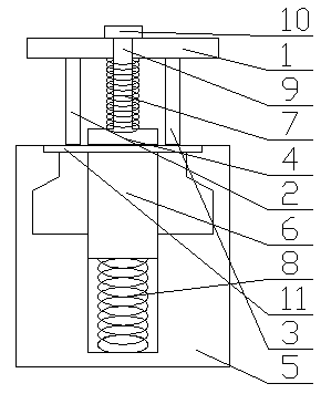
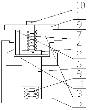
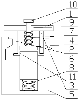
[0014] Such as figure 1 -3, the bending composite mold provided by the present embodiment includes an upper mold base 1, a left punch 2, a right punch 3, a binder plate 4, a die 5, and a ejector block 6, and the left punch 2. The right punch 3 is symmetrically fixed on the upper die base 1, and the binder plate 4 is located between the left punch 2 and the right punch 3 and is movably arranged on the upper die base 1. An elastic body 7 is arranged between the binder plate 4 and the upper mold base 1; the die 5 is provided with a narrow cavity, and the bottom of the narrow cavity is provided with a blind hole, and the ejector block 6 is movably a...


PUM


Abstract

The invention discloses a bent compound die which comprises an upper die holder, a left convex die, a right convex die, a pressure plate, a concave die and an ejection block, wherein the left convex die and the right convex die are symmetrically and fixedly arranged on the upper die holder, the pressure plate is arranged between the left convex die and the right convex die and movably arranged on the upper die holder, and an elastomer 1 is arranged between the pressure plate and the upper die holder; and the concave die is provided with a narrow-mouth cavity, the bottom of the narrow-mouth cavity is provided with a blind hole, the ejection block is movably arranged in the blind hole, and an elastomer 2 is arranged between the ejection block and the bottom of the blind hole. The die disclosed by the invention can realize the one-time forming of flanging U-shaped bending, and is simple in structure, low in production costs, easy to maintain and long in service life, therefore, the die can reduce the production cost.

Description

technical field [0001] The invention relates to the technical field of cold stamping processing, in particular to a bending composite die. Background technique [0002] The U-shaped bending structure of the flanging usually requires two forming processes: the first U-shaped forming, and the second flanging forming. In the prior art, many U-shaped bending composite molds for once-formed flanging are also disclosed, but these composite molds have complex structures, high manufacturing costs, inconvenient maintenance, and short service life, so the production costs are relatively high. It is further improved to provide a mold with a simpler structure to realize one-time forming of the U-shaped bending of the flanging. Contents of the invention [0003] The purpose of the present invention is to provide a bending composite mold, which can realize the one-time forming of the U-shaped bending of the flanging, and has a simple structure, low manufacturing cost, easy maintenance,...

Claims


Application Information

Patent Timeline
IPC IPC(8): B21D37/10
Inventor 叶弥
Owner 安徽吉峰技研有限公司
Why Eureka
Try Eureka