Multifunctional workpiece holder

A workpiece fixture and multi-functional technology, applied in the direction of workpiece clamping devices, manufacturing tools, etc., can solve the problems of low work efficiency, single function of the workpiece chuck, inconvenience of repeated work, etc., to achieve convenient operation, improve work efficiency, and simple structure Effect

Inactive Publication Date: 2013-03-27
贺尔碧格阀业(常州)有限公司
View PDF10 Cites 26 Cited by
  • Summary
  • Abstract
  • Description
  • Claims
  • Application Information

AI Technical Summary

Problems solved by technology

This type of workpiece fixture needs to rotate the screw rod during frequent clamping and loosening operations, which is not convenient for repeated work in large quantities, resulting in low work efficiency
A

Method used


Image

  • Multifunctional workpiece holder
  • Multifunctional workpiece holder
  • Multifunctional workpiece holder

Examples


Embodiment 1)

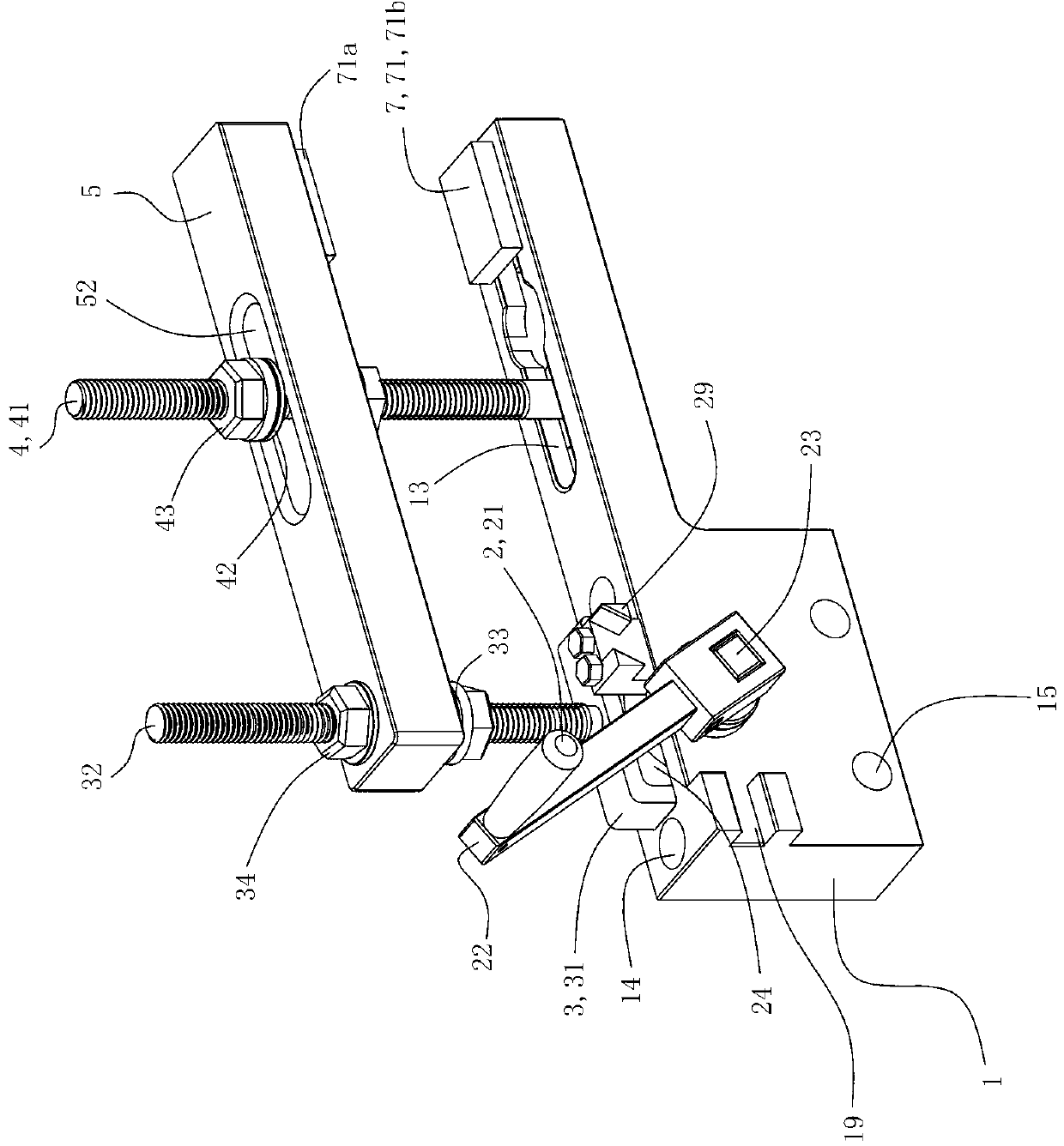
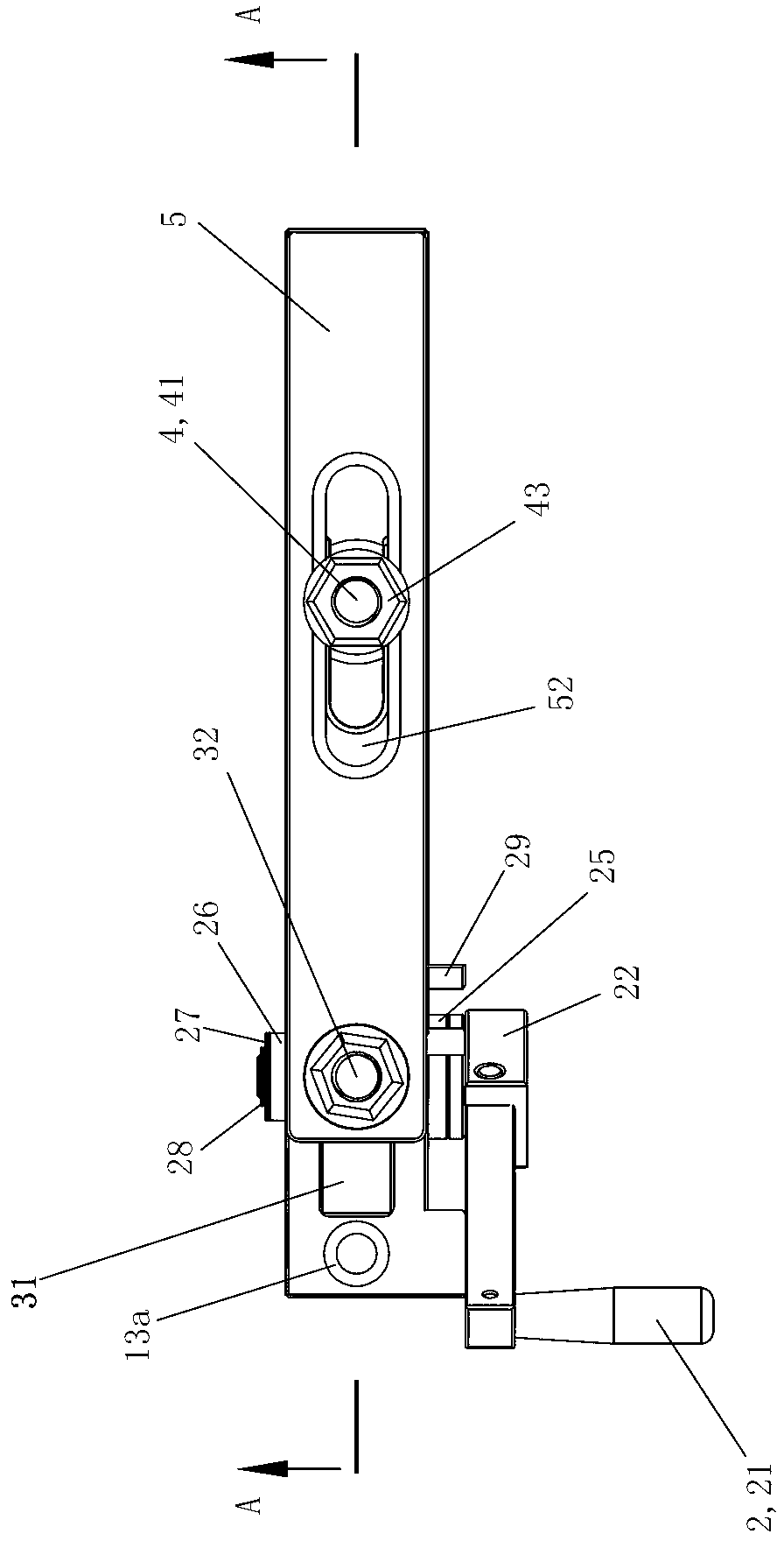
[0069] See figure 1 and Figure 5 , The multifunctional workpiece fixture of this embodiment includes a base 1 , a manipulation assembly 2 , a frame rod assembly 3 , a support rod assembly 4 , a pressure plate 5 , a reset assembly 6 and a pressure head assembly 7 .

[0070] See Figure 5 , Figure 7 Figure 10 and Figure 11, The base 1 is an integral piece made of steel. The left part of the base 1 is provided with a square mounting hole 11 with an upward opening. The left part of the base 1 is also provided with two front and rear rotating shaft installation holes 12 with axes arranged along the front and rear directions and communicating with the square installation hole 11. The two rotating shaft installation holes 12 are divided into front and rear sides according to their front and rear positions. Mounting hole 12-1 and rear side mounting hole 12-2. The front mounting hole 12-1 and the rear mounting hole 12-2 are coaxial, and the diameter of the rear mounting hole...

Embodiment 2)

[0085] The rest of this embodiment is the same as that of Embodiment 1, except that the nut 34 of the frame rod assembly 3 in this embodiment is a spherical shoulder nut, so the frame rod assembly 3 of this embodiment does not have a spherical washer 33 . The nut 43 of the support rod assembly 4 is a spherical shoulder nut, so the support rod assembly 4 of this embodiment does not have a spherical washer 42 .

Embodiment 3)

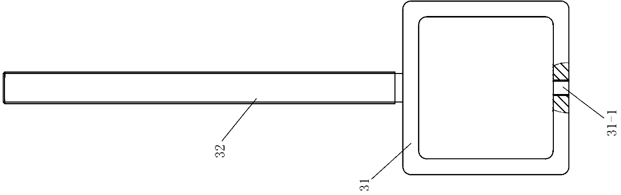
[0087] See Figure 20 , the rest of this embodiment is the same as that of Embodiment 1, except that the reset assembly 6 further includes an end cap 63 . The reset bolt 61 passes through the adjustment hole 17 of the base 1 from bottom to top, and then is screwed into the screw hole 31 - 1 of the transmission frame 31 of the frame rod assembly 3 by the corresponding part of its threaded part. The compression spring 62 is arranged on the underside of the end of the reset bolt 61 , and the end cap 63 is screwed into the adjustment hole 17 of the base 1 to press the compression spring 62 on the lower end of the reset bolt 61 from bottom to top. Turn the pressing plate 5 upwards by 180 degrees, so that its T-shaped slot 53 is located on the upper side of the right end.

[0088] When the present invention is used as a clamping workpiece state, move the handle 21 upwards to make the rocker arm member 22 rotate clockwise 60 degrees with the rotating shaft 23 as the rotating shaft; ...


PUM

PropertyMeasurementUnit
Chamferaaaaaaaaaa

Abstract

The discloses a multifunctional workpiece holder which is characterized by comprising a pedestal, a control assembly, a frame pole assembly, a support pole assembly and a pressing plate, wherein the control assembly mainly comprises a handle, a rocking arm member, a rotating shaft and a driving wheel; the driving wheel is fixed on the forward-backward middle shaft section on the rotating shaft in a tight fit manner and is arranged in a square mounting hole in the pedestal through the rotation of the rotating shaft; one end of the rocking arm member is fixedly connected to the front end of the rotating shaft; the handle is fixedly connected or rotatably connected to the other end of the rotating arm member; the frame pole assembly is vertically arranged in the square mounting hole of the pedestal through a transmission frame of the frame pole assembly and is arranged around the driving shaft; one end of the pressing plate is arranged on a transmission rod of the frame pole assembly and the other end of the pressing plate is arranged on a support bolt of the support pole assembly; and the head of the support bolt of the support rod assembly is arranged in the pedestal. When the multifunctional workpiece holder is used for repeatedly jacking operations, the operations of fixing and loosing workpieces can be rapidly and repeatedly finished just by pulling the handle; and therefore the multifunctional workpiece holder is simple and rapid to operate and greatly improved in working efficiency.

Description

technical field [0001] The invention relates to the field of fixing devices, in particular to a multifunctional workpiece fixture. Background technique [0002] Workholding fixtures are often used to hold a certain part or product to facilitate the assembly or fastening of the product. Most of the current clamps have two clamping blocks, and the two clamping blocks are usually driven by a screw to adjust the distance between the two clamping blocks so as to clamp the object between the two clamping blocks. This type of workpiece fixture needs to rotate the screw rod when performing frequent clamping and loosening operations, which is not convenient for repeated work in large quantities, resulting in low work efficiency. Among them, the portable workpiece chuck of Chinese patent document CN201841484U (patent application number 201020546041.8) belongs to this type of workpiece chuck, and the workpiece chuck has a single function. Contents of the invention [0003] The purp...

Claims


Application Information

Patent Timeline
IPC IPC(8): B25B11/00
Inventor 苏沛群邓志辉
Owner 贺尔碧格阀业(常州)有限公司
Why Eureka
Try Eureka