Automatic ice cream filling machine with cupful ejection function

An ice cream and filling machine technology, applied in packaging machines, packaging, transportation and packaging, etc., can solve the problems of high labor intensity, troublesome extraction, separation of cup lids and paper cups, etc., and achieve the effect of ensuring reliability and hygienic efficiency

Inactive Publication Date: 2014-03-26
常熟威玛乳品机械有限公司
View PDF7 Cites 3 Cited by
  • Summary
  • Abstract
  • Description
  • Claims
  • Application Information

AI Technical Summary

Problems solved by technology

[0004] is not limited to the above exemplified patent solutions, although each has its own advantages, but there are disadvantages that paper cups, egg cones or ice molds are difficult to fully correspond to the filling mechanism
As is well known in the industry, since the filling mechanism (such as the filling nozzle referred to in the patent CN201243597Y) must be in a temporary static state during the filling period, in order to accept the ice cream frozen material poured into the filling mechanism, therefore The movement of the power mechanism needs to meet the stepping requirements. However, due to inertial factors in the alternating phases of movement and short pauses of the power mechanism, it is objectively difficult to ensure that the ice mold or paper cup is aligned directly under the filling mechanism. The feeding position of ice molds or paper cups may be advanced or delayed, which affects the quality of filling cups on the one hand, and causes waste of frozen materials on the other hand.
[0005]Introducing the structure of the cam splitting device into the power mechanism can basically eliminate the above-mentioned shortcomings, but the design and manufacture of the cam are difficult, and the accuracy is difficult to guarantee, especially in the In the process of driving the cam to move by the power mechanism, the cam position may also be deviated due to inertial factors, so the technical scheme similar to that provided by CN2265951Y is rarely used in practice
[0006] In addition, the automatic ice cream filling machine in the prior art removes the paper cup manually after filling the paper cup, which has the disadvantages of troublesome extraction and high labor intensity , and it will also cause the risk of separation of the cup lid and the paper cup during extraction, which will affect hygiene
Because the position of the full cup is usually in the cup hole on the chain plate of the chain rail mechanism, and the edge of the cup tends to be flush with the chain plate 42, only exposing the thickness of the cup cover, which makes it difficult to grasp

Method used


Image

  • Automatic ice cream filling machine with cupful ejection function
  • Automatic ice cream filling machine with cupful ejection function

Examples


Embodiment 1

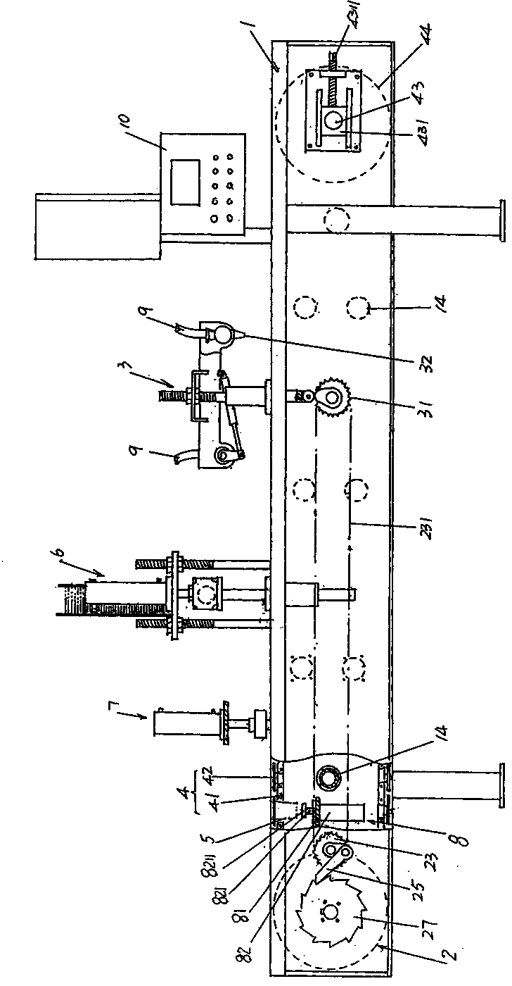
[0024] See figure 1 , a frame 1 is given, a power mechanism 2 is arranged at one end of the frame 1, that is, the left end of the position shown in the figure, and a power mechanism 2 is arranged at the other end of the frame 1, that is, the right end of the position state shown in the figure and corresponding to the frame 1 A filling mechanism 3 is provided at the position above, and the filling mechanism 3 is connected with the power mechanism 2 in transmission, and the paper cup 5 ( figure 2 shown) filling frozen ice cream, and a chain rail mechanism 4 is provided on the frame 1, the chain rail mechanism 4 is connected with the power mechanism 2, and moves around the length direction of the frame 1 under the drive of the power mechanism 2 (line shift). If in order to expand the function of the ice cream automatic filling machine, by figure 1 As shown, the suction cap mechanism 6 and the capping mechanism 7 are set on the frame 1 ( figure 2 shown), the sucked lid is pla...

Embodiment 2

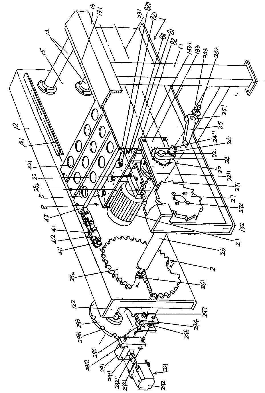
[0038] Not shown, the difference between this embodiment and Embodiment 1 is that the entire inertia canceling device 29 is arranged on the side of the second beam 13 facing away from the first beam 12 , that is, on the side of the second beam 13 facing outward. In this case, the locking disc 293 of the inertia eliminating device 29 is fixed on one end of the large sprocket shaft 26 protruding from the second beam 13, that is to say, the locking disc 293 and the ratchet disc 27 are jointly fixed on the same end of the large sprocket shaft 26. end. Also, in this case, the end of the large sprocket shaft 26 facing the first cross beam 12 basically does not need to protrude from the first cross beam 12 , that is, it remains flush with the outer wall of the first cross beam 12 . The rest are the same as the description of the inertia eliminating device 29 in Embodiment 1.

[0039] applicant combined figure 1 and figure 2 Briefly describe the use of the present invention, the f...


PUM


Abstract

The invention relates to an automatic ice cream filling machine with a cupful ejection function, and belongs to food filling machinery. The automatic ice cream filling machine comprises a frame, a filling mechanism and a chain track mechanism, wherein the frame is composed of a beam bracket, a first beam, a second beam and a group of beam supports; the filling mechanism is arranged at the other end of the frame; and the chain track mechanism is arranged between the first beam and the second beam. The automatic ice cream filling machine is characterized in that a power mechanism comprises a motor, a speed reducing box, a main transmission wheel, a cam, a pawl, a large chain wheel shaft, a ratchet tray, a first large chain wheel, a second large chain wheel and an inertia eliminating mechanism; a cupful ejection mechanism comprises an ejection functioning cylinder bracket and a group of ejection functioning cylinders, wherein one end of the ejection functioning cylinder bracket is fixed to one side of the first beam; the other end of the ejection functioning cylinder bracket is fixed to one side of the second beam; a group of abdicating holes of ejection functioning cylinder columns are formed at the upper part of the ejection functioning cylinder bracket; one group of ejection functioning cylinders are fixed on the ejection functioning cylinder bracket; and expanded ejection heads are arranged on each ejection functioning cylinder column in an expanding manner. Therefore, the chain track mechanism is guaranteed to carry a paper cup to run and stop reliably, and the paper cup is ejected out automatically when paper cup is full. As a result, the automatic ice cream filling machine is sanitary and high in efficiency.

Description

technical field [0001] The invention belongs to the technical field of food filling machinery, and in particular relates to an ice cream automatic filling machine with the function of ejecting a full cup. Background technique [0002] The function of the automatic ice cream filling machine is to automatically fill the ice cream processed by the ice cream machine and introduced by the pipeline. It is an indispensable packaging equipment for a complete ice cream production line. Mechanism composition, the power mechanism is set at one end of the length direction of the frame, the filling mechanism is set at the other end of the length direction of the frame, and is connected with the power mechanism, and the chain rail mechanism is set on the frame, and is connected with the power mechanism. And under the driving of the power mechanism, it moves around the length direction of the frame in a stepping manner from one end to the other end. In the working state, the frozen materi...

Claims


Application Information

Patent Timeline
Patent Type & Authority Patents(China)
IPC IPC(8): B65B43/42B65B61/28B65B65/02B65B3/04
Inventor 白云
Owner 常熟威玛乳品机械有限公司
Why Eureka
Try Eureka