
Hydraulic bucket rod control circuit for hydraulic excavating machine

A hydraulic excavator and control circuit technology, which is applied to mechanically driven excavators/dredgers, mechanical equipment, fluid pressure actuating devices, etc., can solve the limitation of oil return, the amount of recovered oil is small, and the energy saving effect is not obvious. and other problems to achieve the effect of flexible control mode

Active Publication Date: 2015-03-11
SUNWARD INTELLIGENT EQUIP CO LTD
View PDF6 Cites 0 Cited by
  • Summary
  • Abstract
  • Description
  • Claims
  • Application Information

AI Technical Summary

Problems solved by technology

In this kind of stick regeneration control circuit, the regenerative oil port is opened in the valve core, so the oil return volume is limited, and the oil regeneration volume recovered in the stick is relatively small. At the same time, the control of oil return regeneration can only be controlled by sensing the pressure of the rodless cavity. For light load conditions such as flat ground, there is no complete regeneration or regeneration function for different working conditions, and the energy saving effect is not obvious

Method used


Image

  • Hydraulic bucket rod control circuit for hydraulic excavating machine
  • Hydraulic bucket rod control circuit for hydraulic excavating machine
  • Hydraulic bucket rod control circuit for hydraulic excavating machine

Examples


Embodiment Construction

[0019] The present invention will be further described below in conjunction with the accompanying drawings and specific embodiments.

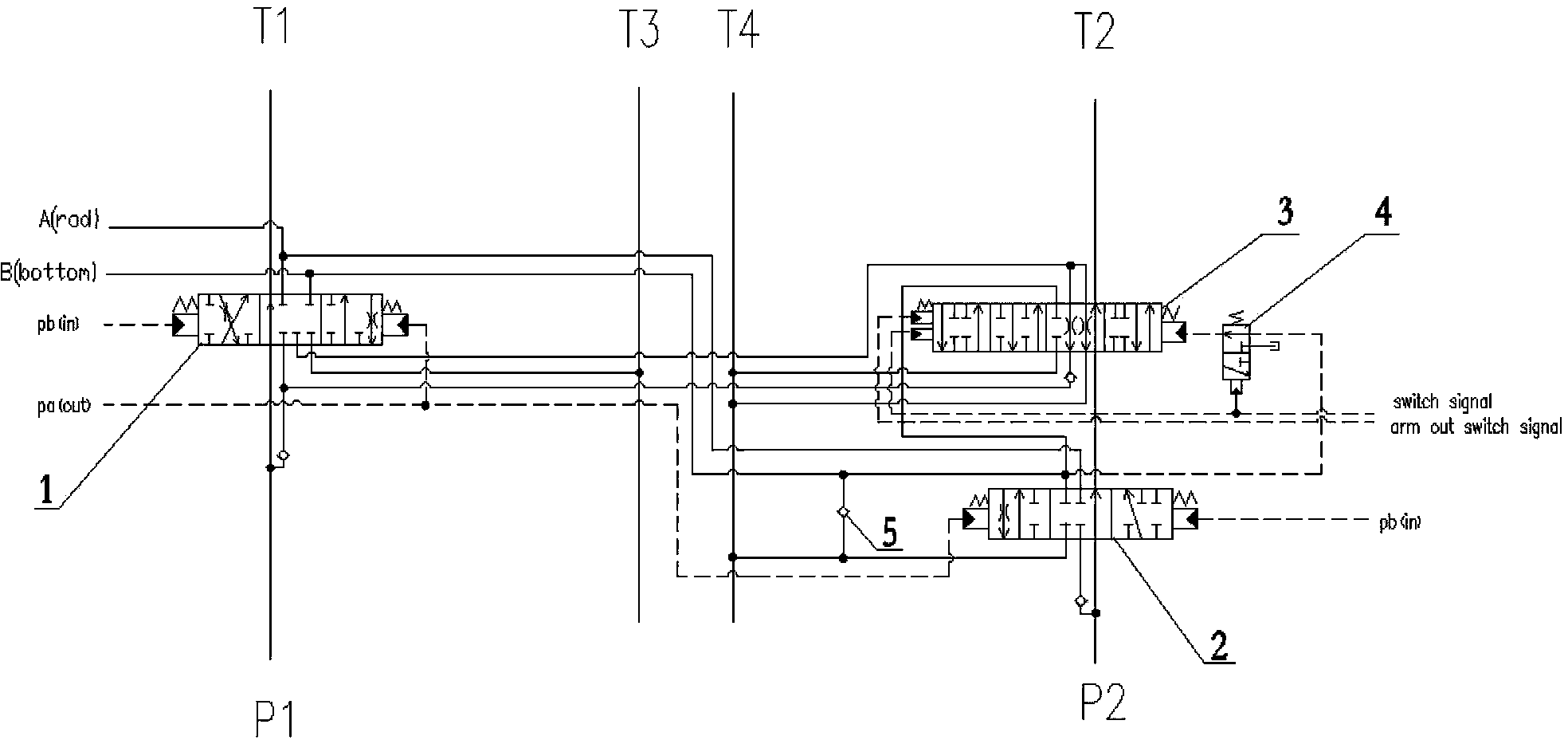
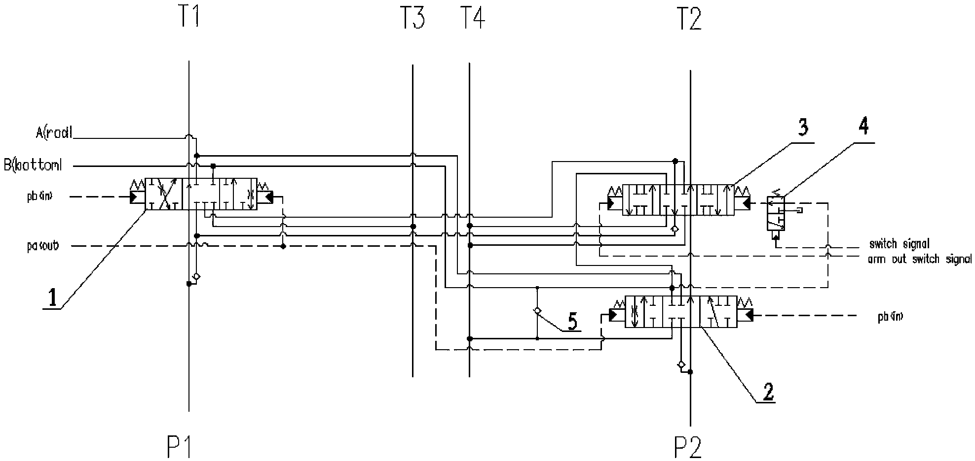
[0020] For the implementation mode 1 of the stick control circuit of hydraulic excavator, please refer to the appendix figure 2 , the circuit is mainly composed of the first stick control valve 1, the second stick control valve 2, the third stick control valve 3, the signal switching valve 4, the second one-way valve 5, etc. through pipeline connections. The first control valve 1 of the stick is a three-position seven-way reversing valve, and the second control valve 2 of the stick is a three-position nine-way reversing valve. When the above two valves are in the neutral position, the system circuit maintains pressure. When the arm swing-out signal acts on the right end of the first control valve 1 of the arm and the left end of the second control valve 2 of the arm, the first control valve 1 of the arm works at the right position, and the sec...


PUM


Abstract

The invention discloses a hydraulic bucket rod control circuit for a hydraulic excavating machine. The hydraulic bucket rod control circuit mainly comprises a first bucket rod control valve, a second bucket rod control valve, a third bucket rod control valve, a signal switching valve and a check valve which are connected with one another by virtue of pipelines. The hydraulic bucket rod control circuit disclosed by the invention is characterized in that one third bucket rod control valve is added on the basis of the existing system, one signal switching valve is used for realizing combined control on oil return of a rod cavity by utilizing a pressure signal of a rodless cavity and an external switch signal, and thus the regeneration of bucket rod return circuit flow corresponding to working conditions outside a valve, regeneration removal and oil supplement for the rodless cavity during complete regeneration are realized. The hydraulic bucket rod control circuit disclosed by the invention has the advantages that firstly, the regeneration outside the valve is controlled by virtue of the third bucket rod control valve, and the regeneration quantity of return oil of a bucket rod is high when the hydraulic bucket rod control circuit is in a complete regeneration position; secondly, the third bucket rod control valve has the regeneration function corresponding to the working conditions, regeneration flow is utilized according to different working conditions, and thus systematic energy conservation in the different working conditions is realized; and thirdly, a regeneration manner is controlled by the pressure of the rodless cavity in the system and also can be controlled by virtue of an external input signal, and the control manner is flexible and can meet the requirements of the different working conditions.

Description

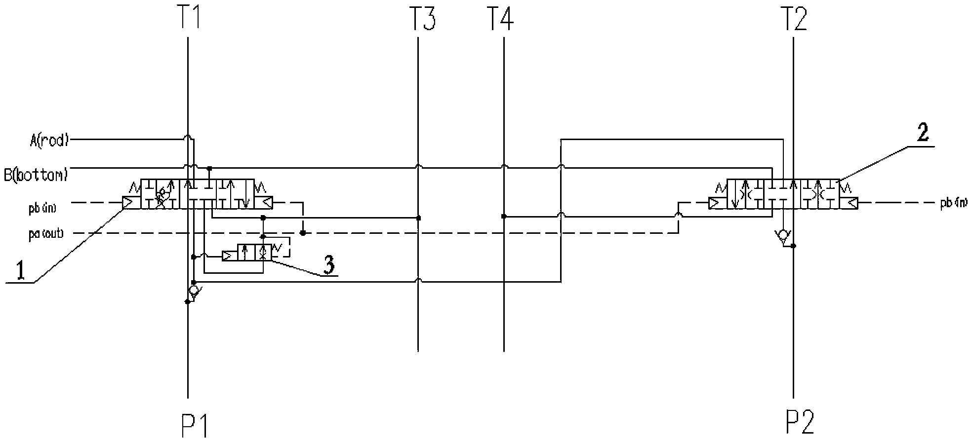
technical field [0001] The invention relates to a stick hydraulic control circuit of a hydraulic excavator, in particular to a hydraulic excavator with the stick retracted and the external valve divided into working conditions for regeneration, regeneration cut-off and complete regeneration without a rod cavity. Background technique [0002] At present, the main control valve of the stick circuit is mainly composed of the first control valve 1 of the stick, the second control valve 2 of the stick, and the regeneration cut-off valve 3. figure 1 shown. The circuit includes a stick outward swing circuit, a stick retracting circuit, and a stick regeneration circuit. Generally, the return oil of the hydraulic cylinder in the hydraulic excavator must be returned to the oil tank. If only part of the return oil of the hydraulic cylinder returns to the oil tank, the rest of the flow will merge with the pressure oil output by the pump and flow into the oil inlet chamber of the hydrau...

Claims


Application Information

Patent Timeline
Patent Type & Authority Patents(China)
IPC IPC(8): E02F3/43F15B13/02
Inventor 何清华郭勇张新海陈桂芳管伟
Owner SUNWARD INTELLIGENT EQUIP CO LTD
Learn More