
Labor-saving machine

A force machine and lever technology, applied in the field of labor-saving machinery, can solve the problems of unfavorable medium-high speed rotation, large resistance, no power balance device, etc., and achieve the effect of simple structure

Inactive Publication Date: 2013-03-27
王明义
View PDF6 Cites 0 Cited by
  • Summary
  • Abstract
  • Description
  • Claims
  • Application Information

AI Technical Summary

Problems solved by technology

[0002] In a currently known labor-saving machine, there is no power balance device, the rear connecting rod is cylinder-piston type, the center of the short arm of the lever and the center of the rear crankshaft are oblique lines, and the rear connecting rod is inclined, which is not conducive to medium and high-speed rotation , lack of resistance

Method used


Image

  • Labor-saving machine
  • Labor-saving machine
  • Labor-saving machine

Examples


Embodiment Construction

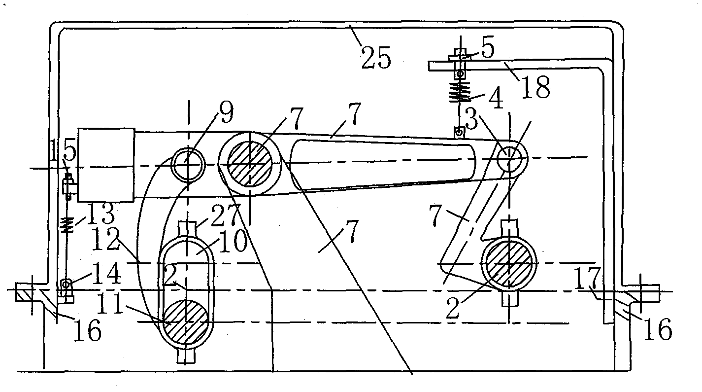
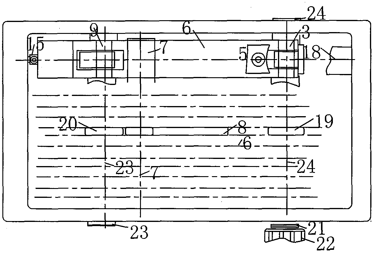
[0012] exist figure 1 Among them, the shaft of the front connecting rod 1 is set at an angle with the rod hole, and the movable pin shaft 3 of the front crank shaft 2 must be continuously connected with one end of the long arm of the lever 6, and the spring 4 is fastened with the adjustment bolt 5 of the lever 6 and the spring bracket 18 respectively. Part 17 is connected on the box body 16, and support shaft 7 is a through shaft that passes in the hole of support frame 8, and the bottom plate of support frame 8 is connected with the bottom plate of box body 16, and rear connecting rod 12 shafts are curved upper ends with dynamic The pin shaft 9 is movably connected in the hole at the short arm end of the lever, and the lower end is connected with the bottom of the long hole 10 of the rear connecting rod. It is connected with the adjustment bolt 15 and the spring seat 14 on the side of the box body 16. The front crankshaft 24 and the rear crankshaft 23 are installed on both si...


PUM


Abstract

The invention discloses a labor-saving machine which is assembled with a dynamic balance device, is provided with an arc rear connecting rod and does not need a starting device. The labor-saving machine is formed by connecting a front crankshaft, a front connecting rod, the dynamic balance device, a lever, the arc rear connecting rod, a rear crankshaft, the lever, a supporting axle, a bearing and a support box body continuously. The levers can be directly utilized to enable the rear crankshaft to start rotating along with the front crankshaft, the two crankshafts rotate at the same speed, so that energy resources are saved for times.

Description

Technical field [0001] The invention relates to a labor-saving machine, in particular, a dynamic balance device is installed at both ends of a lever, which can prevent the machine from vibrating when the unbalanced lever moves at high speed. Background technique [0002] In a currently known labor-saving machine, there is no power balance device, the rear connecting rod is a cylinder piston type, the center of the short arm of the lever is oblique to the center of the rear crankshaft, and the rear connecting rod is inclined, which is not conducive to medium and high speed rotation , The lack of large resistance. Contents of the invention [0003] In order to overcome the deficiencies in the existing labor-saving machine, the present invention provides a labor-saving machine, which is not only equipped with a dynamic balance device, the rear connecting rod adopts an arc-shaped shaft, the shaft hole is a long hole, and the front connecting rod The shaft and the shaft hole f...

Claims


Application Information

Patent Timeline
IPC IPC(8): F16H21/10
Inventor 王明义
Owner 王明义
Learn More