Optical sheet, backlight unit for liquid crystal display apparatus and method for manufacturing optical sheet

A technology of optical sheets and optical functional layers, which is applied in the field of optical sheets, can solve problems such as the decrease of front brightness, and achieve the effect of improving quality and excellent optical functions

Active Publication Date: 2015-03-25
KEIWA INCORPORATED
View PDF4 Cites 0 Cited by
  • Summary
  • Abstract
  • Description
  • Claims
  • Application Information

AI Technical Summary

Problems solved by technology

[0006] However, in the aforementioned resin bead-coated light-diffusing sheet 44, in order to improve the light-diffusing performance and to make the brightness uniform, etc., it is necessary to increase the amount of resin beads 50 added, but if the amount of resin beads 50 added is increased, , it will lead to a decrease in the brightness of the front

Method used


Image

  • Optical sheet, backlight unit for liquid crystal display apparatus and method for manufacturing optical sheet
  • Optical sheet, backlight unit for liquid crystal display apparatus and method for manufacturing optical sheet
  • Optical sheet, backlight unit for liquid crystal display apparatus and method for manufacturing optical sheet

Examples


Embodiment approach

[0083] The optical sheet of the present invention is not limited to the above-described embodiments, and the following embodiments may be employed.

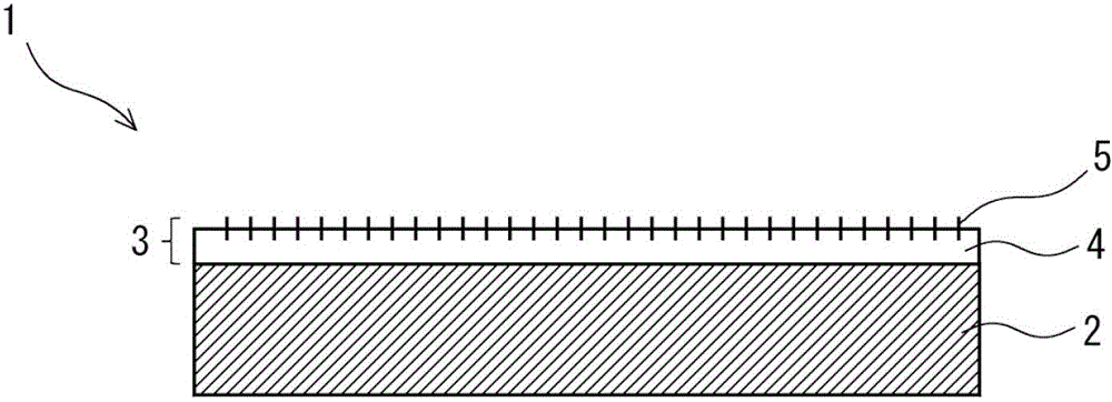
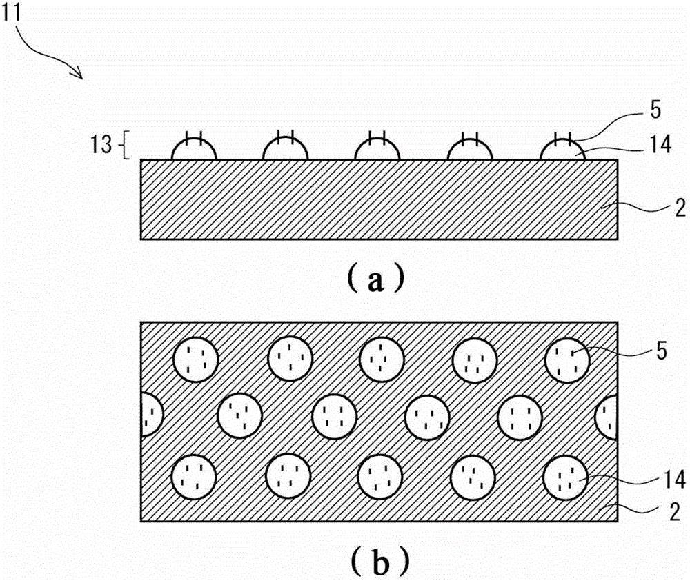
[0084] image 3 The optical sheet 11 is a so-called light diffusion sheet, and includes a base material layer 2 and an optical function layer 13 arranged on the surface of the base material layer 2 . The optical function layer 13 includes: an adhesive part 14 ; a plurality of fibers 5 protruding from the base material layer 2 through the adhesive part 14 ; and air sandwiched between the plurality of fibers 5 . The base material layer 2, the manufacturing method of the sheet, the adhesive agent forming the adhesive portion 14, the material of the fiber 5, etc. are the same as those described above. figure 1 The optical sheets 1 are the same, so their descriptions are omitted.

[0085] The plurality of fibers 5 protrude from the surface of the base material layer 2 through the plurality of adhesive portions 14 provided in scatte...

Embodiment 1

[0103] An adhesive ("E263" manufactured by Dainichi Seika Co., Ltd.) was coated on the surface of the substrate layer by a roll coating method, and polyamide fibers were implanted by electrostatic tufting. The material of the substrate layer is polyethylene terephthalate, and the thickness is 100 μm. The surface density of the fiber substrate layer is 3500 fibers / cm 2 , with an average diameter of 10 μm and an average length of 50 μm.

[0104] The optical sheet of Example 1 was irradiated with a backlight, and the total light transmittance was measured in accordance with JIS K7361, and the result was 79%. In addition, haze was measured in accordance with JIS K7105, and the result was 86%.

Embodiment 2

[0106] Using the same substrate layer and adhesive as in Example 1, polyester fibers were implanted by electrostatic hair transplantation. The density of the surface of the fiber substrate layer is 3000 fibers / cm 2 , with an average diameter of 10 μm and an average length of 50 μm.

[0107] The optical sheet of Example 2 was irradiated with a backlight, and the total light transmittance was measured in accordance with JIS K7361, and the result was 82%. In addition, haze was measured in accordance with JIS K7105, and the result was 87%.


PUM

PropertyMeasurementUnit
diameteraaaaaaaaaa
lengthaaaaaaaaaa
thicknessaaaaaaaaaa

Abstract

Provided is an optical sheet capable of exhibiting superior optical function, and a high-quality backlight unit using the same. The optical sheet includes a transparent substrate layer, and an optical function layer having a plurality of fibers protruding from one surface side of the substrate layer. The optical function layer preferably includes an adhesive portion joining the plurality of fibers to the substrate layer. The adhesive portion is preferably laminated entirely on the one surface side of the substrate layer. The adhesive portion is preferably formed from acryl emulsion adhesives. The refractive index of the fiber is preferably no less than 1.3 and no greater than 1.8. The density of the fiber per unit area in the plane direction of the substrate layer is preferably no less than 100 fibers / cm2 and no greater than 5000 fibers / cm2.

Description

technical field [0001] The present invention relates to an optical sheet, a backlight unit using the same, and a manufacturing method of the optical sheet. Background technique [0002] As a transmissive liquid crystal display device, a backlight system in which the liquid crystal layer is irradiated from the back is popularized, and edge-light type (side-light type), direct-light type, and other backlight units are provided on the lower side of the liquid crystal layer. Such as Figure 7 As shown, the edge light type backlight unit 40 is generally equipped with a lamp 41 as a light source, a square plate-shaped light guide plate 42 disposed along the lamp 41 at the end, and a light guide plate 42 on the surface of the light guide plate 42. A plurality of optical sheets 43 stacked on one side. LEDs (Light Emitting Diodes) or cold cathode tubes are used as the lamp 41 as a light source, but LEDs are now becoming popular from the viewpoint of miniaturization and energy saving...

Claims


Application Information

Patent Timeline
Patent Type & Authority Patents(China)
IPC IPC(8): G02F1/13357F21V5/08F21S8/00F21Y101/02
CPCG02B6/0065G02F1/1336G02B6/0025G02B5/0221G02B6/0005G02B6/0078G02B5/02G02B5/04G02F1/1335
Inventor 辻孝弘
Owner KEIWA INCORPORATED
Why Eureka
Try Eureka