Vacuum concentrator

A vacuum concentrator, heater technology, applied in evaporator accessories, chemical instruments and methods, evaporation, etc., can solve problems such as solvent loss and vacuum equipment damage

Inactive Publication Date: 2013-04-03
王良源
View PDF6 Cites 6 Cited by
  • Summary
  • Abstract
  • Description
  • Claims
  • Application Information

AI Technical Summary

Problems solved by technology

[0007] The technical problem to be solved by the present invention is that the vacuum system in the prior art is easy to suck out the condensate close to the main vacuum pipe, thus easily causing the loss of solvent and the damage of vacuum equipment, and then proposes a vacuum system that prevents or reduces the suction of the vacuum system. concentrator

Method used


Image

  • Vacuum concentrator
  • Vacuum concentrator
  • Vacuum concentrator

Examples


Embodiment 1

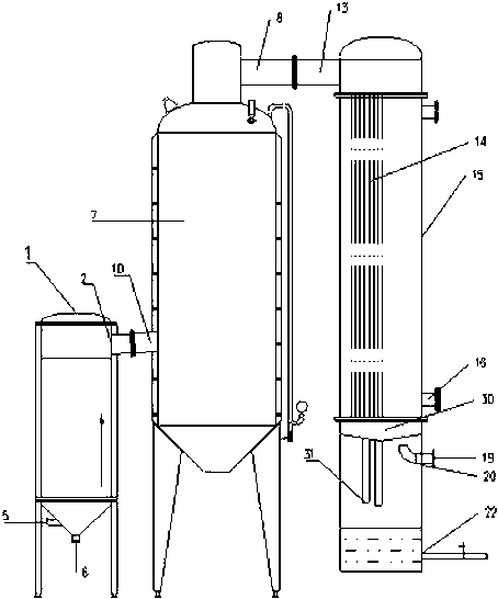
[0051] Vacuum concentrator of the present invention such as figure 1 As shown, a heater 1 is included, and the heater 1 is provided with a feed port 5, and the position of the feed port 5 can be selected according to needs. In this embodiment, the feed port 5 is arranged at the The lower part of the heater 1; the upper part of the heater 1 is provided with an air outlet 2, in this embodiment, the air outlet 2 is arranged on the top of the heater 1; material outlet 6, the position of the concentrated material outlet 6 can be selected according to needs, in this embodiment, the concentrated material outlet 6 is arranged at the bottom of the heater 1; the heater 1 is any commercially available The heater 1, its heating mode is any mode that can be realized, preferably electric heating and steam heating etc., in the present embodiment, described heater 1 is electric heater;

[0052] An evaporator 7, the evaporator 7 is provided with a steam inlet 10, the position of the steam inl...

Embodiment 2

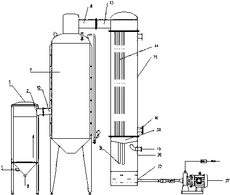
[0059] Such as figure 2 As shown, the vacuum concentrator described in this embodiment is based on the above embodiments, the drain port 22 is connected with a drain pump 27, and the condensed liquid collected in the liquid chamber passes through the drain pump 27 through the drain port 22 Discharge; the distance between the vacuum tube 19 and the outlet 31 of the liquid outlet becomes 700mm.

Embodiment 3

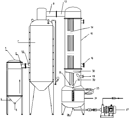
[0061] Such as image 3As shown, on the basis of the above-mentioned embodiments, the vacuum concentrator in this embodiment also includes a liquid receiving tank 24, and the liquid receiving tank 24 is arranged below the liquid collector 20. In this embodiment, The distance between the vacuum tube 19 and the liquid outlet pipe outlet 31 is set to 900mm; the bottom of the liquid collector 20 is connected to the top of the liquid receiving tank 24; the liquid receiving tank 24 is provided with a liquid inlet 23 And liquid outlet 26, in the present embodiment, described liquid inlet 23 is arranged on the top of described liquid receiving tank 24, and described liquid outlet 26 is arranged on the bottom of described liquid receiving tank 24; The discharge port 22 of the device 20 communicates with the inside of the liquid receiving tank 24 through the liquid inlet 23; the liquid outlet 26 is connected with the drain pump 27; and, the liquid collector 20 The bottom is an inverted...


PUM


Abstract

The invention discloses a vacuum concentrator. The vacuum concentrator comprises a heater and an evaporator, wherein a gas outlet of the heater is communicated with a steam inlet of the evaporator; a condensing passage is arranged inside a condenser; a steam outlet of the evaporator is communicated with an inlet of the condensing passage; a liquid collector is arranged below the condenser; the condensing passage stretches into the liquid collector from the top of the liquid collector; a vacuum tube is arranged on the liquid collector; the distance between the vacuum tube and an outlet of the condensing passage is proper when condensate flows out of the outlet of the condensing passage and is not brought out of the liquid collector by a vacuum system; a liquid draining port is connected with a water draining pump; and the outlet of the condensing passage is positioned above the liquid surface of the condensate inside the liquid collector. The vacuum concentrator can be used for concentrating liquid materials in chemical, pharmaceutical and food industries and the like.

Description

technical field [0001] The invention relates to a vacuum concentrator, which belongs to the technical field of evaporation equipment. Background technique [0002] In the chemical, pharmaceutical and food technical fields, it is often necessary to concentrate the feed liquid. The concentrator is just the equipment used to evaporate the solvent in the feed liquid and extract high-purity feed liquid. Concentrators are divided into atmospheric concentrators and high-pressure concentrators according to their pressures. For atmospheric concentrators, in order to improve their concentration efficiency, a higher concentration temperature is required, which also increases energy consumption accordingly; When the material contains heat-sensitive substances, the heat-sensitive substances are easily denatured at high temperature, which affects the stability of the concentrated product quality. [0003] In order to overcome the above shortcomings of atmospheric concentrators, the resea...

Claims


Application Information

Patent Timeline
Patent Type & Authority Applications(China)
IPC IPC(8): B01D1/00B01D1/30
Inventor 吴学文张详安吴荣源赵明桥
Owner 王良源
Why Eureka
Try Eureka