Mineral separator and use method thereof
A technology for separators and minerals, applied in the field of machinery, can solve the problems of affecting work efficiency, loss of sieve holes to screen minerals, etc., and achieve the effects of improving work efficiency, reducing maintenance, and not easy to block
- Summary
- Abstract
- Description
- Claims
- Application Information
AI Technical Summary
Problems solved by technology
Method used
Image

Examples
Embodiment 1
[0042] It is now stipulated that the coarse ore with a diameter larger than the user's demand is fine, and the mineral with a diameter less than or equal to the user's demand is fine ore. For example, if the user needs a mineral with a fineness of 100 mesh or more, the mineral with a fineness of less than 100 mesh is coarse ore, and the mineral with a fineness of 100 mesh or more is fine ore.
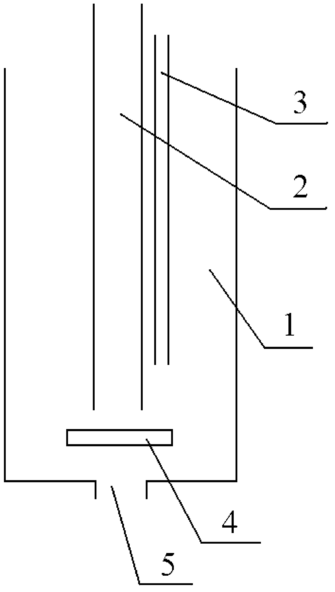
[0043] figure 1 Is a cross-sectional view of the mineral separator provided in the first embodiment of the present invention, see figure 1 As shown, it includes: a separation drum 1, a water inlet pipe used to inject water into the separation drum 1, an inlet pipe 3 used to inject minerals into the separation drum 1, and a water inlet pipe used to make the water in the separation drum 1 occur In the separation drum 1, a rotary hydraulic generator 4 that rotates around the side wall of the separation drum 1; wherein the bottom of the separation drum 1 is provided with a coarse ore outflow ho...
Embodiment 2
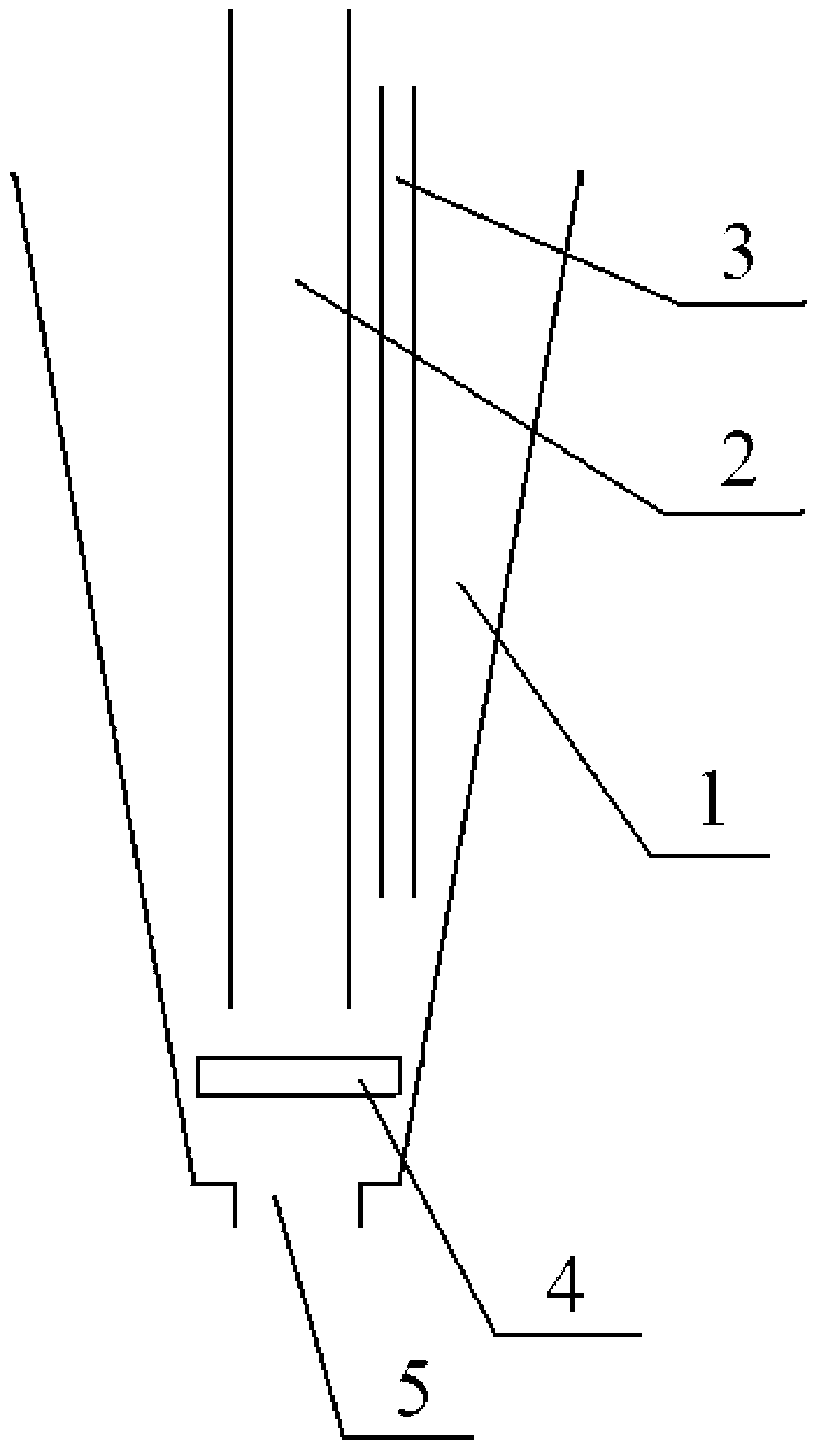
[0047] figure 2 This is a cross-sectional view of the mineral separator provided in the second embodiment of the present invention. On the basis of the above-mentioned embodiment 1, see figure 2 As shown, the separation cylinder 1 has an inverted cone shape.
[0048] In the second embodiment, the separation drum 1 is an inverted cone. Therefore, when the water in the separation drum 1 rotates around the side wall of the separation drum 1 by the rotating hydraulic generator, the diameter of the lower part of the separation drum 1 is smaller than that of the separation drum. The diameter of the upper part, so when the rotating hydraulic generator makes the water rotation force unchanged, and the rotating space is smaller, the water in the separation drum 1 can rotate more quickly around the side wall of the separation drum, and the generated rotation force is more Large, can better separate coarse ore from fine ore. The fine ore can better rotate with the water to a higher positi...
Embodiment 3
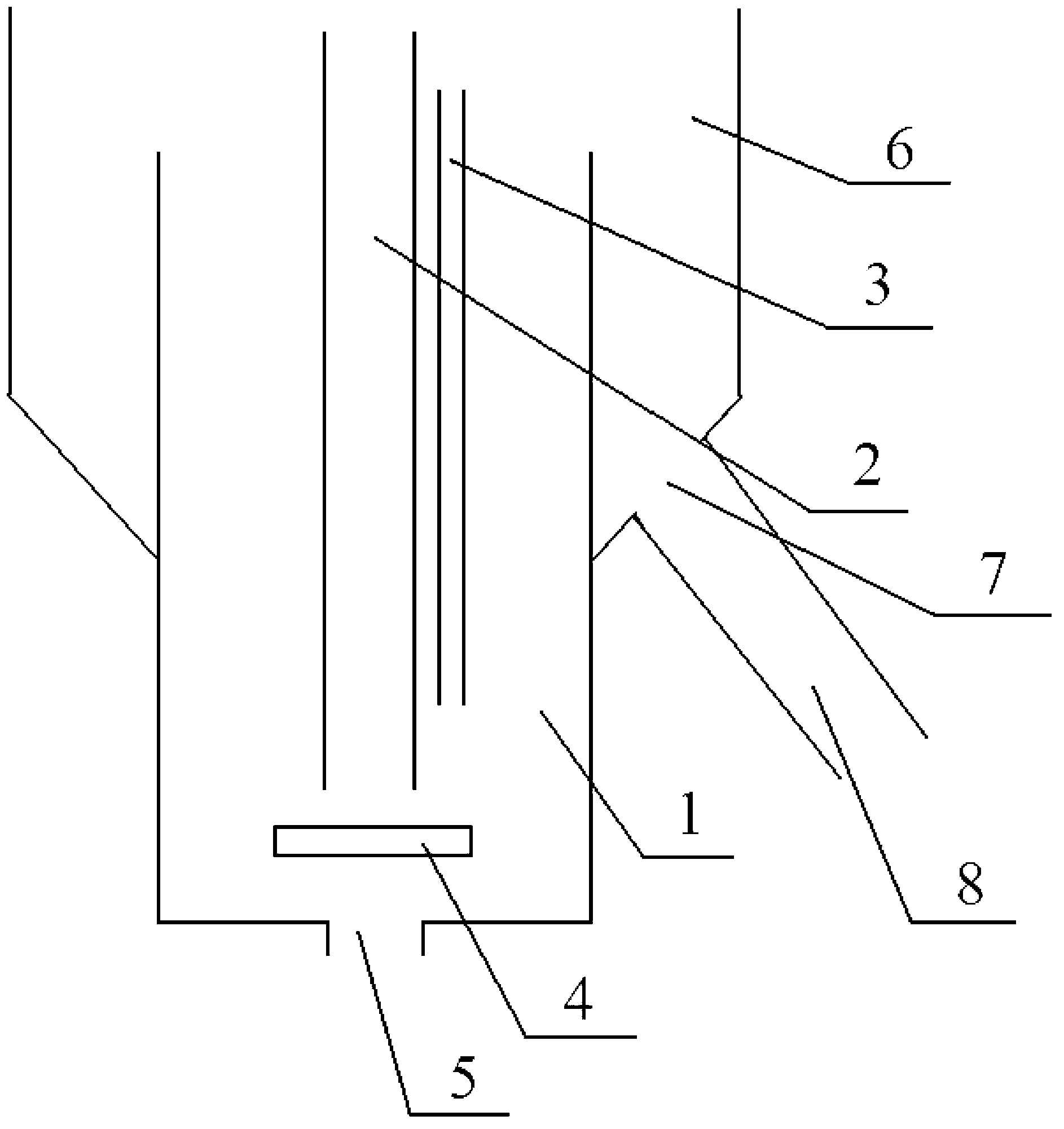
[0051] image 3 This is a cross-sectional view of the mineral separator provided in the third embodiment of the present invention. On the basis of the above-mentioned first and second embodiments, see image 3 As shown, the separation drum 1 is also sleeved with a fine ore discharge drum 6; the diameter of the fine ore discharge drum 6 is larger than the diameter of the separation drum 1; the upper edge of the fine ore discharge drum 6 is higher than the The upper edge of the separation drum 1; the side wall of the fine ore discharge drum 6 is also provided with a fine ore outflow hole 7.
[0052] In the third embodiment, because the fine ore overflows from the upper part of the separator cylinder 1, it is difficult to collect. The required collection device must be able to include all the upper part of the separator cylinder 1. Connect the fine ore discharge drum 6, and the diameter of the fine ore discharge drum 6 is larger than the diameter of the separation drum 1, and its upp...
PUM
 Abstract
Description
Claims
Application Information
 - Generate Ideas
- Intellectual Property
- Life Sciences
- Materials
- Tech Scout
- Unparalleled Data Quality
- Higher Quality Content
- 60% Fewer Hallucinations
Browse by: Latest US Patents, China's latest patents, Technical Efficacy Thesaurus, Application Domain, Technology Topic, Popular Technical Reports.
© 2025 PatSnap. All rights reserved.Legal|Privacy policy|Modern Slavery Act Transparency Statement|Sitemap|About US| Contact US: help@patsnap.com